
CNC machining and inspection equipment: how parts are routed and verified.
Compare milling, turning and grinding resources with dimensional, surface and material checks. Tecpreva confirms equipment allocation from the drawing and inspection plan.
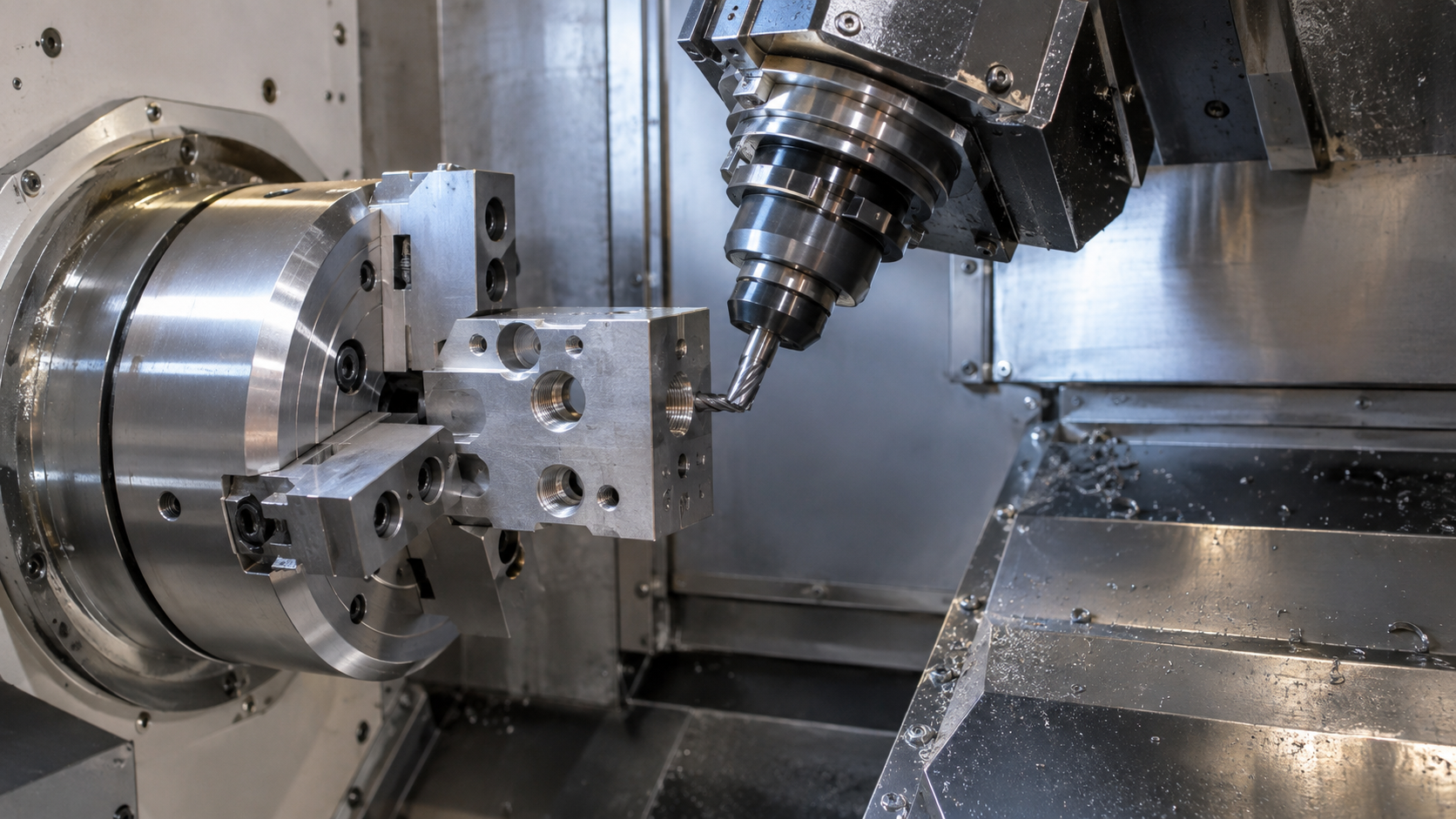
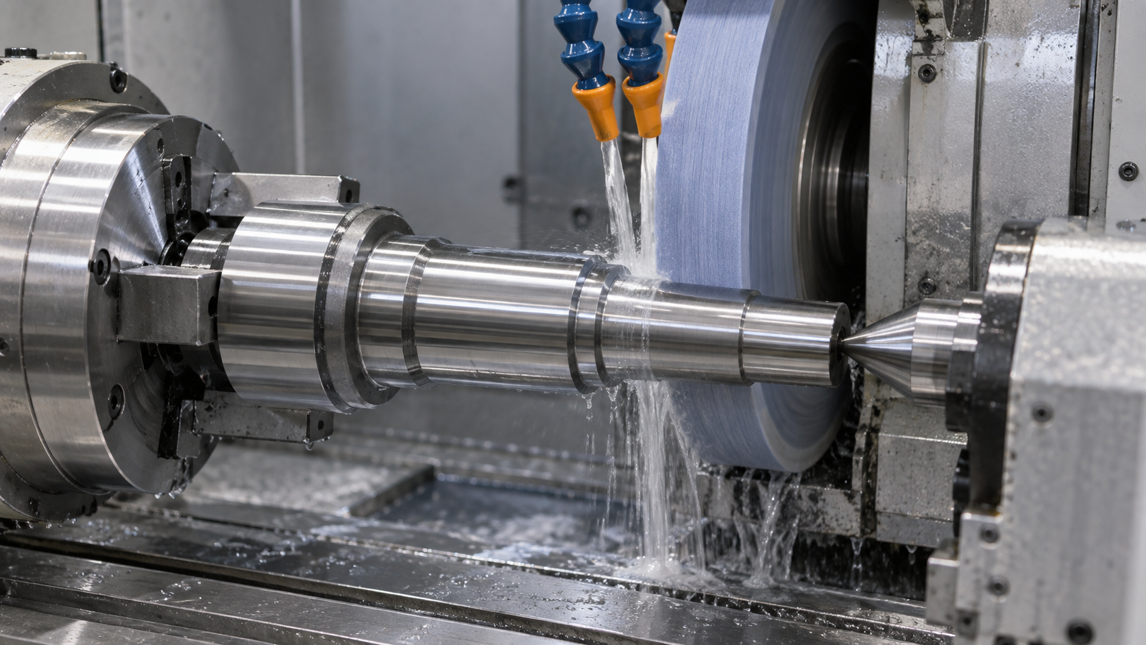
Start with part geometry rather than a machine count. Milling resources address faces, pockets and hole patterns; turning addresses rotational features; grinding can support final fits after heat treatment. Match inspection methods to the datum scheme, feature accessibility and accepted tolerance. Confirm special equipment requirements, machine availability and measurement scope during quotation.
CNC machining equipment
Machine specifications do not guarantee finished-part tolerances. Review material, workholding, cutting access, temperature, tool wear and the measurement method together. Equipment quantities below describe the existing local data; part suitability is confirmed separately. Finished-part tolerance is confirmed from the drawing, not from the machine row.
| Equipment type | Model | Brand | Quantity | Typical capability | Typical use |
|---|---|---|---|---|---|
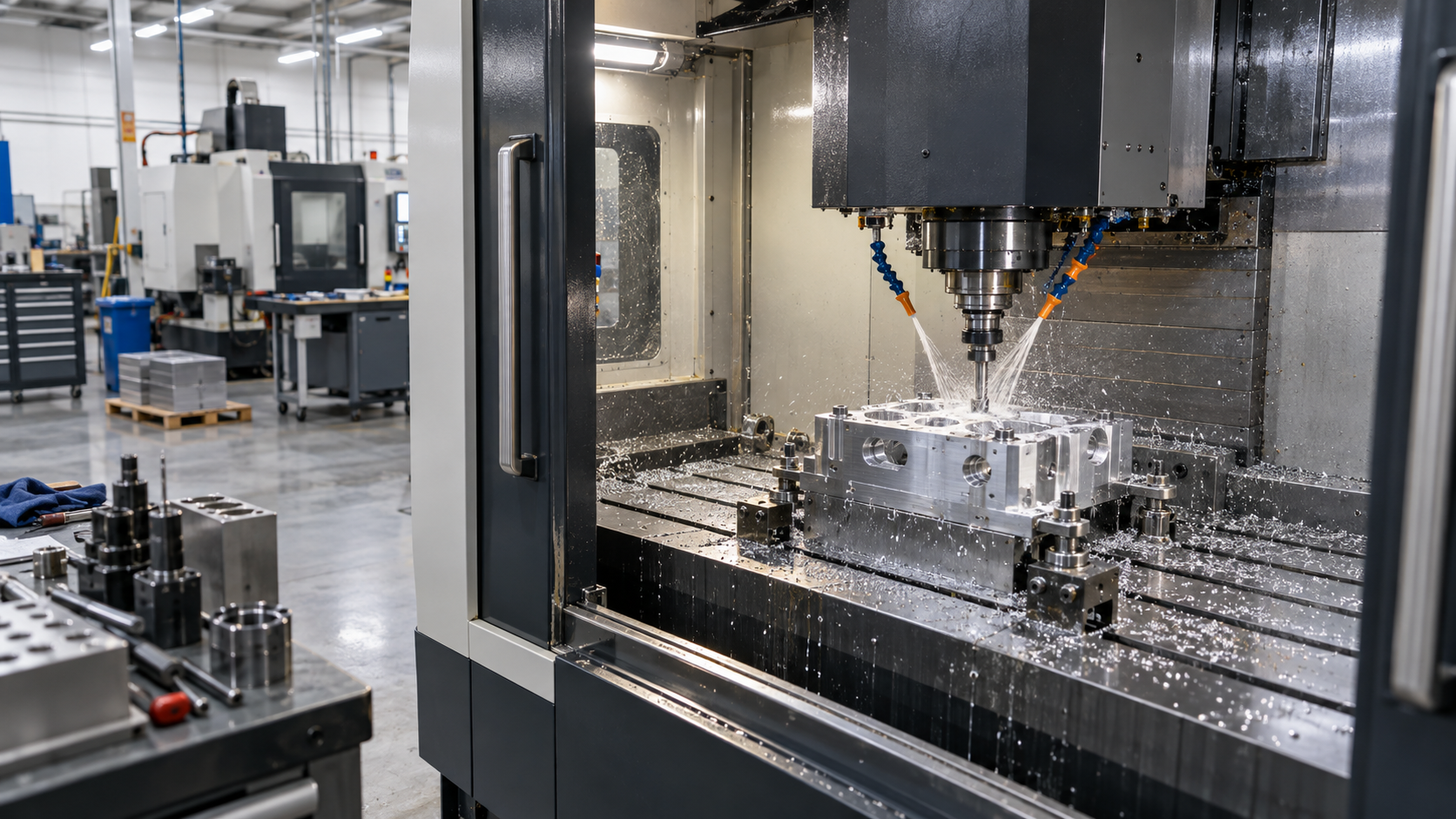
| 3-axis CNC machining center | HAA5 | Cincinnati | 9 | ±0.01 mm | Prismatic parts, pockets, drill patterns and basic contouring across aluminium, steel and engineering plastics. |
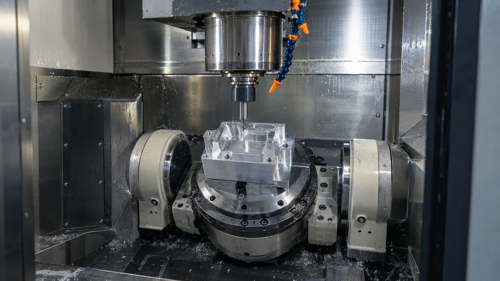
| 4-axis CNC machining center | VL3 / AV3 | TSUGAMI | 5 | ±0.01 mm | Prismatic parts with a rotary fourth axis for indexed features, hole patterns around a shaft and simple wrapped contours. |
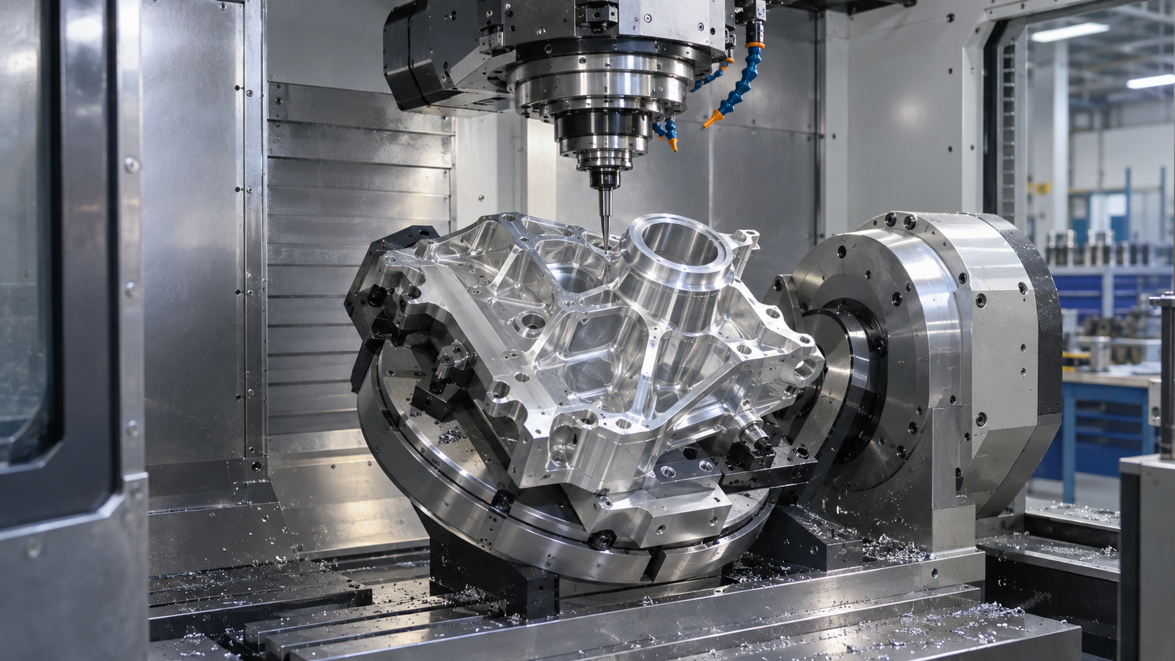
| 5-axis CNC machining center | S-PIUS8 / YHV1165 | Huaya CNC | 2 | ±0.005 mm | Angled features, complex geometry and reduced re-clamping across aerospace, medical and optical components. |
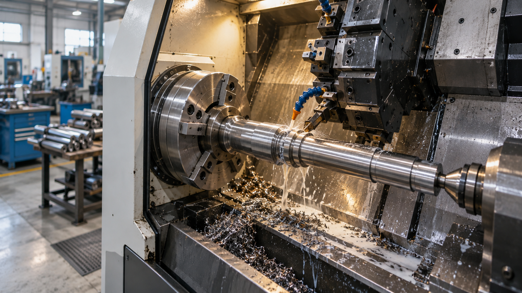
| CNC turning center | HTC3650 | SMTCL | 3 | ±0.01 mm | Shaft-type turned components, faced features and concentric tolerances for fluid-power and motion-control parts. |
| Turning-milling center | M08SY-II | TSUGAMI | 1 | ±0.01 mm | Turned blanks with milled cross-features in one setup — fewer re-clampings for hydraulic manifolds and instrument bodies. |
| CNC grinding machine | 618S | KENT | 1 | ±0.002 mm | Surface and cylindrical grinding for hardened tool-steel parts where milling accuracy is no longer enough. |
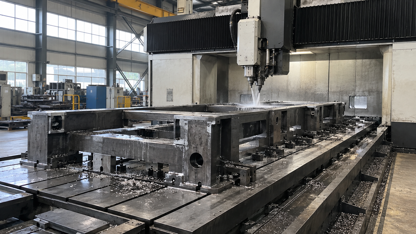
| Large-format machining center | YHV1165 | Huaya CNC | 1 | ±0.02 mm | Oversized frames, jigs and structural panels that exceed the envelope of our standard machining centers. |
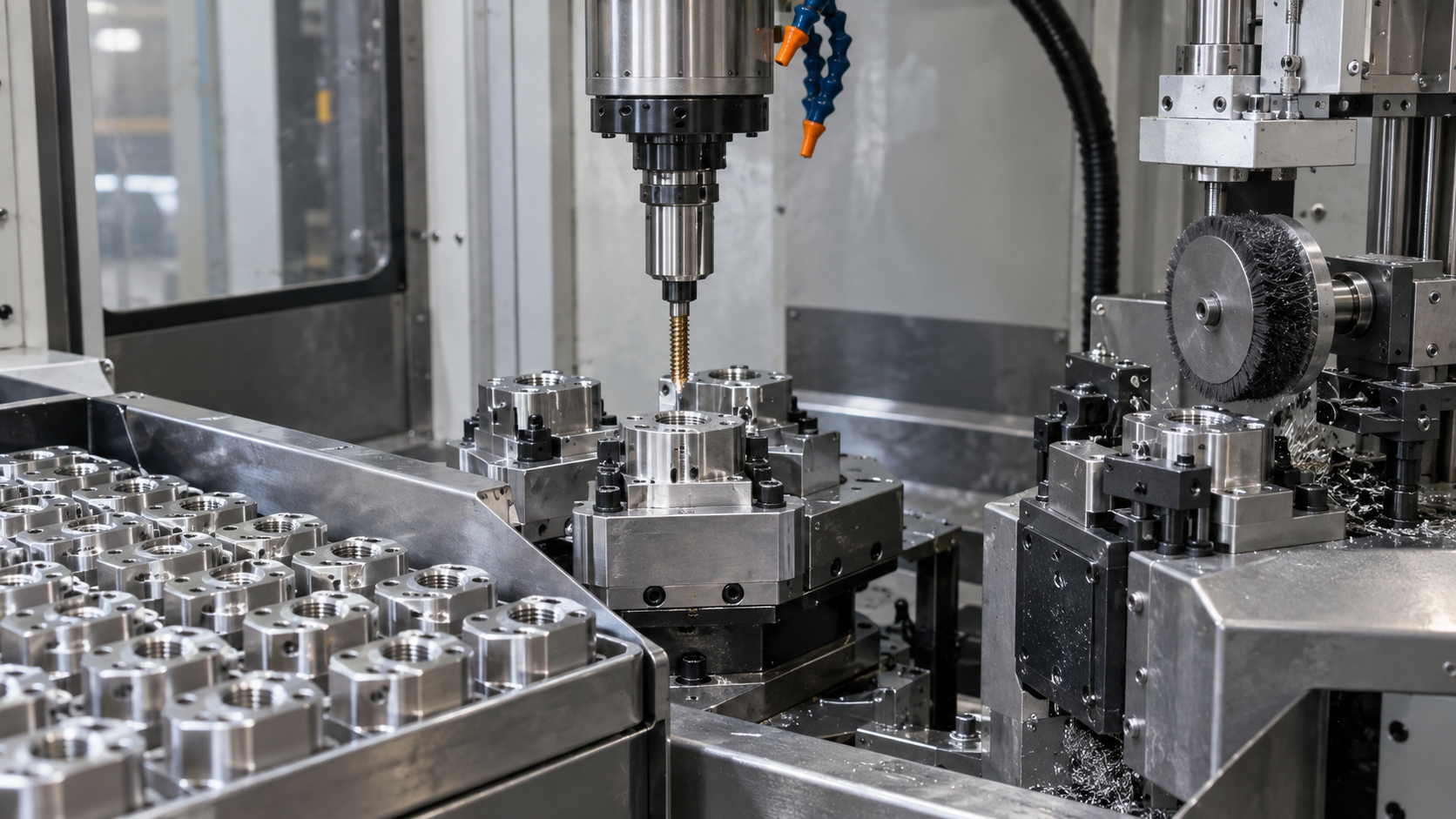
| Automatic tapping / secondary operation equipment | T500 / T600 / T700 | Doosan | 1 | ±0.05 mm | High-volume tapping, deburring and light secondary operations moved off the machining centers to keep spindle hours on cutting. |
Inspection equipment
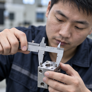
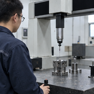
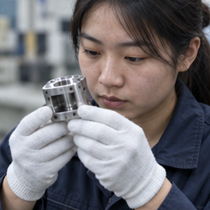
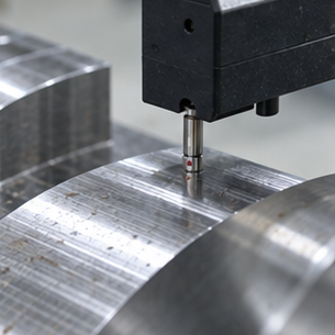
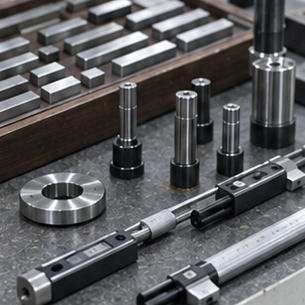
CMM checks suit datum-related geometry; gauges suit diameters and threads; roughness, hardness and coating checks address different acceptance requirements. Specify characteristic numbers, sampling, report format and any customer-supplied inspection procedure. Brand, measuring range, quantity and accuracy are published after the nameplate is checked.
| Inspection equipment | What it verifies | How it is used | Available documentation |
|---|---|---|---|
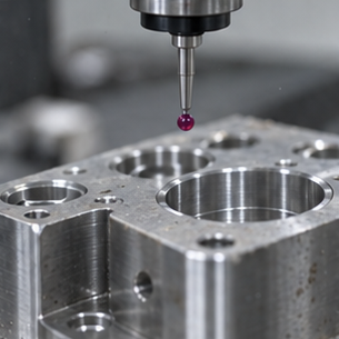
| Coordinate measuring machine (CMM) | Complex dimensions, datum relationships, position and profile | Brand/model, measuring range, quantity and accuracy will be published after the machine nameplate and calibration record are verified. | First-article or dimensional report when agreed |
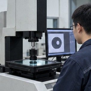
| Vision measuring machine / optical projector | Small profiles, edge features, hole positions and optical geometry | Used for features better evaluated optically than with contact gauges. | Dimensional inspection record when agreed |
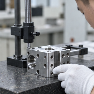
| Height gauge and granite surface plate | Heights, steps, parallel surfaces and in-process reference dimensions | Used for controlled setup and in-process dimensional checks. | In-process or final inspection record when agreed |
| Surface roughness tester | Specified Ra surface-finish requirements | Used where a drawing identifies a measurable surface-finish requirement. | Surface-finish record when agreed |
| Hardness tester | Material condition or post-treatment hardness | Used when the drawing or material specification calls for hardness verification. | Hardness record when agreed |
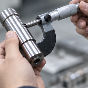
| Calibrated micrometers, bore gauges, thread gauges and pin gauges | Diameters, bores, threads and feature-specific dimensions | Selected to match the feature, tolerance and measurement method in the control plan. | Inspection record when agreed |
| Coating thickness tester | Coating thickness where specified | Used for applicable plated or coated parts where thickness verification is required. | Coating-thickness record when agreed |


Capability highlights
- 23machines in the published machining inventory
- 12material families in the public catalogue
- 6common surface-finishing routes
- 3 / 4 / 5-axismachining routes
- 1 business dayinitial engineering response
- Drawing-reviewedquotation and sample timing
Quality documentation
- Drawing revision confirmation
Provided as agreed — every revision received is acknowledged before tooling is changed.
- Material traceability
Provided when specified — mill certificate or heat-traceable material records per lot.
- First-article and dimensional reports
Provided when agreed — full FAIR / dimensional report against your STEP model and control plan.
- Batch identification and shipment documentation
Provided when agreed — lot / batch identifiers, packing lists and COC / CofA are prepared to the confirmed shipment scope.
- Manufacturing route and inspection scope
Confirmed before production — the machining sequence, critical controls and agreed measurement records are aligned with the drawing and order requirements.
Upload drawings for equipment review
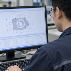
Send the 2D drawing, STEP model, material condition, quantity and critical dimensions. Identify any required CMM report, surface reading, hardness check or coating verification so the process and inspection scope can be reviewed.