

Why Select This Process
Compared with repeated manual setups, controlled rotary indexing can reduce handling and preserve the relationship between features on different faces. It can also simplify parts that are awkward to fixture as a series of separate 3-axis operations.
Frequently Asked Questions
When is 4-axis the right choice over 3-axis?
When a part has features on multiple faces, radial holes, or wrap-around geometry that would require multiple re-clampings on a 3-axis machine, the 4th axis reduces setups, improves accuracy, and often shortens cycle time.
Do you use a trunnion or a horizontal rotary table?
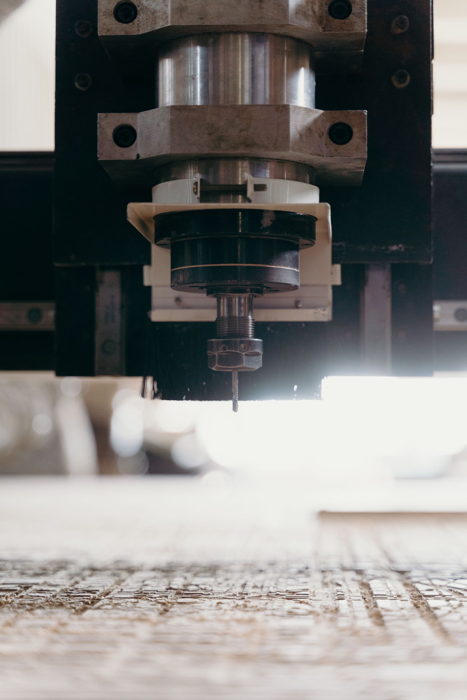
Both. A trunnion is preferred for cubic parts with machined features on the sides; a horizontal rotary table is preferred for cylindrical or symmetric parts. The choice is made from the model and the critical datums.
Do you handle threads, taps, and reaming on 4-axis parts?
Yes. Thread milling, rigid tapping, and reaming are all supported along any axis. Standard metric (M), UNC / UNF, and BSP threads are common; specialty threads are reviewed case-by-case.
Shipping options
- DHL / FedEx / UPS — international express, 3 – 5 business days door-to-door, full tracking and customs handling.
- Air freight — 5 – 10 business days for heavier or consolidated shipments.
- Ocean freight (FCL / LCL) — 20 – 35 days for non-urgent production runs.
- Customer-arranged courier — parts released to a customer-provided account on request.
- EXW, FOB, CIF, DAP — Incoterms supported per customer preference.
Axis motion | Linear X, Y, Z plus one rotary axis |
|---|---|
Ideal geometry | Multi-side and radial features |
Key benefit | Reduced re-clamping for angular alignment |
Review input | Angular datum, CAD model, drawing, and tolerances |
Standard Tolerances & Achievable Precision
Default tolerances follow ISO 2768-m. On 4-axis work, the indexing accuracy of the rotary axis directly affects angular tolerance, so the table below is reviewed against the chosen machine configuration.
- Standard linear tolerance — ±0.05 mm
- Precision tolerance — ±0.025 mm on critical features
- Tight tolerance — ±0.01 mm by review
- Angular positioning — ±0.05— typical; ±0.01— achievable with qualified rotary table
- True position of radial holes — ? 0.05 mm at MMC typical
- Concentricity / runout — 0.03 mm TIR on turned-and-indexed features
Process Flow
The machining sequence should be planned around the part's functional datums, feature access, material behavior, and the required inspection method. The detailed route is ultimately governed by the actual machine configuration, workholding, tool availability, and production quantity.
Process Stage | Purpose |
|---|---|
1. Input review | Confirm the 3D model, drawing, material, critical dimensions, datums, quantity, and finish requirements. |
2. Setup plan | Select workholding, datum strategy, cutting tools, machining order, and access to all functional features. |
3. Machining | A typical route starts by defining the primary datum and rotary-center relationship. The part is then held in a rotary fixture, chuck, or collet. The program sequences face operations, indexing moves, radial drilling, slotting, contouring, and finishing passes so that related features retain their intended angular location. |
4. Verification | Inspection typically focuses on hole position, angular spacing, concentricity to the rotary datum, runout, feature depth, and any critical surface finish. The inspection plan should identify the common axis or datum system that controls related features. |
Design Intent
The design should establish a stable rotary datum and identify the angular relationship between all critical features. Workholding, tool reach, part balance, and access to the clamped face should be reviewed before choosing the machining route.
ENGINEERING INPUT ?Provide a 3D CAD model, a drawing with critical tolerances and datums, the material grade, requested quantity, surface finish, and any inspection or packaging requirements. |
|---|
Part Geometry and Materials
Material Selection
Aluminum is common for lightweight fixtures and housings; stainless steel and alloy steel are selected for strength or corrosion resistance; brass, copper, titanium, and engineering plastics may be used when the functional requirement calls for them.
Material group | What to consider | Typical reason for selection |
|---|---|---|
Aluminum | Machinability, thermal movement, cosmetic finish. | Lightweight housings, brackets, fixtures, heat-management parts. |
Steel & stainless | Strength, corrosion resistance, heat, chip control. | Industrial, structural, fluid-system, precision mechanical parts. |
Brass, copper & titanium | Conductivity, corrosion, strength-to-weight, cost. | Fittings, electrical parts, high-performance or specialized components. |
Engineering plastics | Stiffness, temperature, chemical environment, burr control. | Insulating, lightweight, prototype, wear or fluid-contact parts. |
MATERIAL NOTE:The material must be selected against functional needs first. Machinability, heat, corrosion, weight, cost, and the desired surface treatment should then be reviewed together. |
|---|
Technical Planning and Quality
Before Production
A manufacturability review should confirm that the tolerance scheme is functional, the specified material is available, the workholding leaves access to critical faces, and the measurement plan can verify all requirements without ambiguity. Where an assembly interface is critical, provide the mating-part information or fit requirement.
DRAWING PRACTICE ?Call out the dimensions that matter to function. Avoid applying an unnecessarily tight general tolerance where only a limited number of features control the fit, motion, sealing, or alignment of the final assembly. |
|---|
Application Context
Automation, electronics, robotics, industrial machinery, instrumentation, fluid handling, and prototype development are frequent use cases for 4-axis work.
Application family | Where the process adds value |
|---|---|
Prototype and product development | Useful where a functional part, review sample, or process route must be validated before a larger production decision. |
Industrial and automation equipment | Supports durable custom hardware, fixtures, housings, interfaces, shafts, passages, and assembly features. |
Precision and regulated equipment | Supports geometry that must be documented through clear datums, material specifications, inspection requirements, and controlled finishing. |
When to Choose Another Process
Choose 4-axis milling when a single rotary axis gives sufficient access. When the part needs compound-angle access, sculpted surfaces, or continuous motion around more than one rotational axis, 5-axis machining may be the more appropriate route.
QUOTE CHECKLIST ?Include model and drawing files, material grade, order quantity, material certification needs, finishing requirements, critical features, and target delivery date with the RFQ. |
|---|
Materials We Machine
4-axis work commonly uses the same material set as 3-axis milling, with special attention to machinability when the rotary motion is engaged on long wraps.
- Aluminum alloys — 6061, 7075, 2024, 5052, 6063
- Stainless steel — 304, 304L, 316, 316L, 17-4 PH (H900 / H1025 / H1075 conditions)
- Carbon & alloy steel — 1018, 1045, 4140, 4340 pre-hardened, A36
- Brass & copper — C360 brass, C110 copper, C954 aluminum bronze
- Titanium — Grade 2, Grade 5 (Ti-6Al-4V)
- Engineering plastics — Delrin, PEEK, PTFE, nylon, polycarbonate, HDPE
- Tooling materials — O1, A2, D2 tool steel for fixtures and wear parts
Quality Control & Inspection
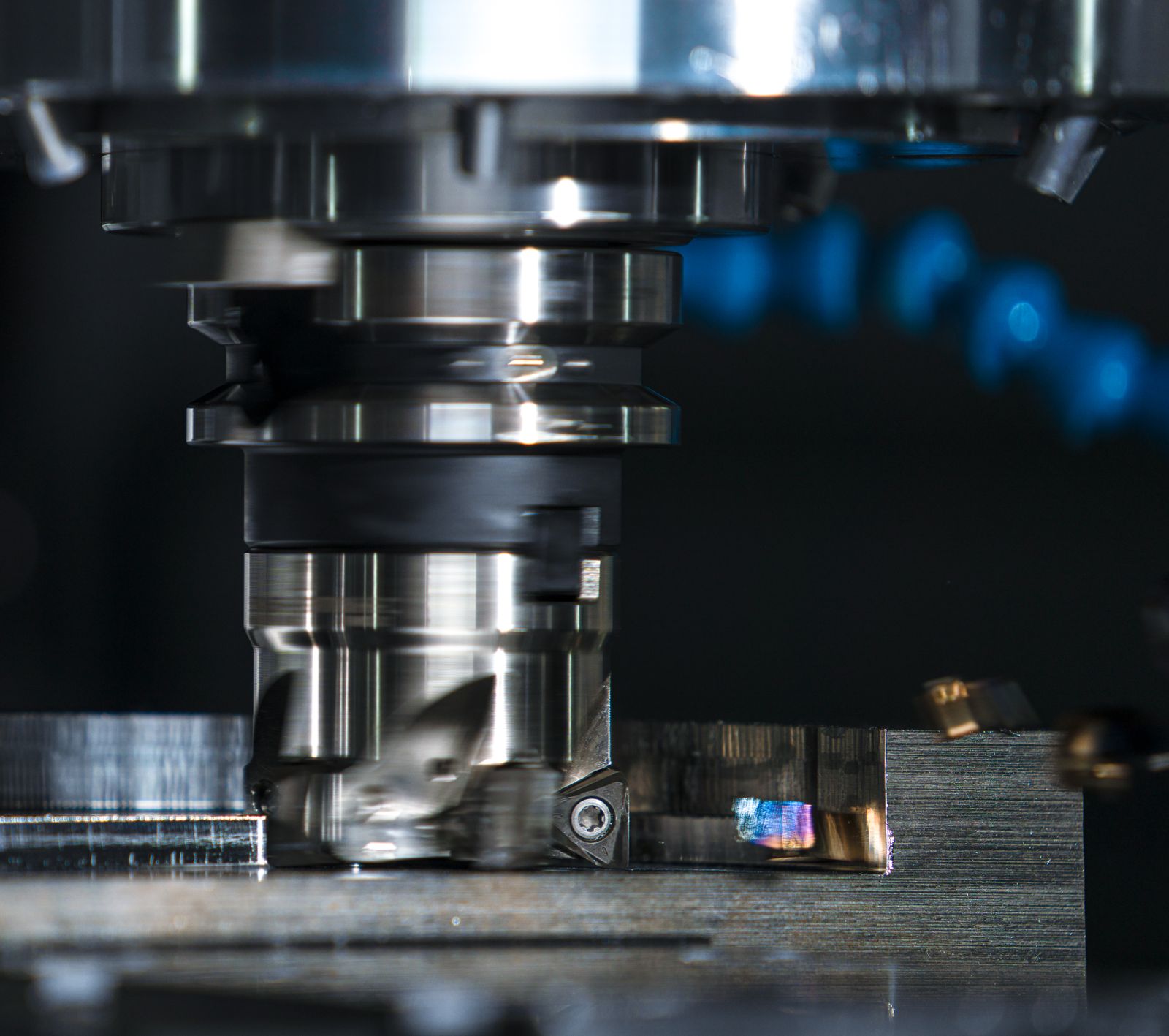
4-axis work often involves angular features and radial geometry, so inspection is built around angular measurement in addition to standard dimensional checks.
- First-article inspection (FAI) — 100 % dimensional check on the first part, AS9102 format on request
- CMM inspection — Zeiss or equivalent, including angular datum alignment and rotary-axis feature verification
- Surface roughness tester — Mitutoyo SJ-210 or equivalent
- Hardness tester — Rockwell / Vickers for material and heat-treat condition
- Protractor & sine plate — for in-process angular verification
- Caliper / micrometer / pin gauge — calibrated hand tools at the cell
- Final inspection report — dimensional, material, and finish records supplied on request
How to Get a Quote
To quote accurately, send a 3D model (STEP / IGES), a 2D drawing (PDF / DWG) with critical tolerances, the material grade, requested quantity, finish or coating, any inspection or documentation requirements, and the target delivery date. Within one business day we return DFM feedback, a clear lead time, and a unit / total price. An NDA can be signed before any file exchange if needed.
Process Flow & Manufacturing Sequence
4-axis work adds a rotary axis (A or B) to the standard 3-axis sequence. The fourth axis is used either as a positioning trunnion or as a continuous rotary table, and the workflow is built around minimizing the number of re-clampings.
- Material receiving & verification — incoming stock is checked against the purchase order, MTC is logged, and the heat lot number is recorded for full traceability.
- Stock cutting — band saw cuts stock to blanks, leaving 1 – 3 mm of machining allowance per face.
- Workholding selection — for trunnion work, soft jaws, fixture plates, or a 4-jaw chuck are used. For rotary table work, a 3-jaw / 4-jaw chuck, collet, or vacuum fixture is chosen based on the part geometry and required datum.
- Datum establishment & initial facing — a face mill establishes a clean reference face, and the part is probed to verify position relative to the machine origin. The rotary axis is zeroed on the chosen datum centerline.
- Rough milling (linear axes) — heavy material removal on the primary 3-axis faces using indexable end mills, trochoidal paths, or high-efficiency roughing strategies.
- Rough milling (rotary axis engaged) — features on multiple faces or around a cylinder are roughed out by indexing the rotary axis to each working angle, reducing the number of separate setups.
- Semi-finish inspection — pilot dimensions, datum alignment, and the centerline of rotation are verified before the finishing pass.
- Semi-finish milling — walls and floors are brought to within 0.1 – 0.2 mm of nominal on each face to leave a uniform stock for finishing.
- Drilling, tapping & reaming — holes are produced along any of the 4 axes, with rigid tapping and thread-milling cycles for fastener and thread features. Standard drills and reamers are used wherever possible.
- Finishing pass (linear + rotary) — a low-engagement finishing pass brings all features to final dimension, holding tighter tolerances and meeting the surface finish callout (typically Ra 0.8 – 1.6 µm).
- Edge break & chamfer — 0.2 – 0.5 mm chamfer applied to sharp edges per print, with a chamfer mill or by hand on cosmetic features.
- Deburring & cleaning — hand deburring, tumble, or brush deburr followed by aqueous wash to remove coolant, chips, and oil.
- Final inspection — first-article inspection on the first part, then in-process or sample inspection across the batch. Angular features are verified on a CMM with the rotary datum aligned.
- Outsourced surface treatment (if applicable) — anodize, plating, powder coat, passivation, and similar processes routed to qualified partners.
- Packaging & shipping — parts wrapped, bagged, labeled, and packed per customer specification, with documentation enclosed.
Material Property Reference
The reference data below covers materials routinely cut on our 4-axis cells. The machinability rating helps compare cycle time and tool wear across grades. Lot-specific values are confirmed by the mill certificate (MTC).
Material | Density (g/cm?) | Tensile Strength (MPa) | Yield Strength (MPa) | Hardness (HB) | Machinability (%) |
|---|---|---|---|---|---|
Aluminum 6061-T6 | 2.70 | 310 | 276 | 95 | 180 |
Aluminum 7075-T6 | 2.81 | 572 | 503 | 150 | 170 |
Stainless 304 | 8.00 | 515 | 205 | 170 | 45 |
Stainless 316L | 7.99 | 485 | 170 | 160 | 40 |
17-4 PH (H1025) | 7.78 | 1,070 | 1,000 | 330 | 30 |
Carbon Steel 1018 | 7.87 | 440 | 370 | 130 | 70 |
Alloy Steel 4140 | 7.85 | 655 | 415 | 200 | 55 |
Brass C360 | 8.50 | 400 | 140 | 80 | 100 |
Copper C110 | 8.94 | 220 | 70 | 45 | 85 |
Titanium Grade 5 | 4.43 | 950 | 880 | 340 | 22 |
Tool Steel O1 | 7.81 | 650 (annealed) | 380 (annealed) | 200 | 45 |
Delrin (POM) | 1.41 | 70 | 65 | 120 (R) | 150 |
Machinability ratings are relative to AISI 1212 steel = 100%. HB values in (R) for plastics denote Rockwell, not Brinell.
What drives cost
- Material — the same material cost as 3-axis work, but rotary-axis cycles are often longer on tough alloys, so machinability has a bigger effect.
- Tolerance — angular tolerance, concentricity, and runout are limited by the rotary axis accuracy (±0.01— to ±0.05—); tighter callouts require a higher-end table and CMM verification.
- Batch size — programming and fixture cost is amortized across the run; short batches carry a larger setup premium than long runs.
- Geometry complexity — multi-face parts, radial features, and wrap-around geometry benefit most from 4-axis; simple prismatic parts do not need the rotary axis.
- Workholding — trunnion or rotary-table fixtures are typically custom and amortized across the batch.
- Surface finish & coating — features on multiple faces complicate masking and finishing; outsourcing cost may be higher than for a single-face 3-axis part.
- Inspection & documentation — angular features are checked on a CMM, which is more expensive than hand-gauge inspection.
What drives lead time
- Material sourcing — common bar / plate sizes in 2 – 5 days; specialty alloys 2 – 4 weeks.
- Programming & fixture build — 4-axis CAM and trunnion fixture design typically add 1 – 2 days over a comparable 3-axis part.
- CNC cycle time — index moves and longer tool engagement on rotary faces add to cycle time; high-efficiency roughing mitigates this.
- Outsourced processes — anodize, plating, powder coat, and heat-treat are 2 – 7 business days at qualified partners.
- CMM inspection & documentation — angular verification on a CMM with the rotary datum aligned typically adds 1 – 2 days.
- Shipping — DHL / FedEx international 3 – 5 days; ocean freight 20 – 35 days; air freight 5 – 10 days.
Typical lead times by scenario
Scenario | Prototype (1 – 5 pcs) | Low-volume (10 – 100 pcs) | Production (500+ pcs) |
|---|---|---|---|
Stock material on hand | 5 – 7 business days | 7 – 10 business days | 10 – 15 business days |
Material to be sourced | 7 – 12 business days | 12 – 18 business days | 18 – 28 business days |
With outsourced finish (anodize, plating, coating) | 9 – 14 business days | 12 – 20 business days | 20 – 32 business days |
With full FAI / AS9102 / PPAP documentation | + 2 – 4 business days | + 1 – 3 business days | + 1 – 2 business days |
Standard packaging
- VCI bag — applied to all ferrous parts to prevent oxidation in transit and storage.
- Foam wrap or foam-lined trays — protects machined surfaces and threads from contact damage.
- Compartmentalized plastic trays — for small parts in production quantities.
- Cardboard cartons with internal partitions — standard for medium and small parts.
- Custom plywood crates — for large, heavy, or precision parts above 25 kg, with foam lining and edge protection.
- ESD-safe packaging — for parts that integrate into electronics or semiconductor equipment.
- Labeling — part number, lot / batch, quantity, material, and customer reference on every outer and inner package.
Standard documentation
- Certificate of Conformance (C of C) — confirms parts were manufactured to the print and meet specified requirements.
- Mill Test Certificate (MTC) — material certificate retained for every heat lot.
- First-article inspection report (FAI / AS9102) — 100 % dimensional report on the first part, including angular verification.
- Dimensional inspection report — recorded measurements of critical features across the batch.
- Surface finish report — Ra measurements where called out.
- Certificate of Origin (CoO) — for customs clearance.
- Commercial invoice & packing list — standard shipping documentation.
- PPAP / APQP package — for automotive customers, including control plan, PFMEA, and capability data.
What the Process Does
4-axis CNC milling adds one rotary axis to the X, Y, and Z linear movements used in standard milling. The added axis lets the workpiece be indexed at controlled angles or moved around a rotary surface, helping the cutter reach features that would otherwise require repeated re-clamping. It is often chosen for components with radial holes, wrapped patterns, multi-sided faces, and cylindrical sections with milled features.
Quality and Inspection
Inspection typically focuses on hole position, angular spacing, concentricity to the rotary datum, runout, feature depth, and any critical surface finish. The inspection plan should identify the common axis or datum system that controls related features.
Surface Finish and Part Protection
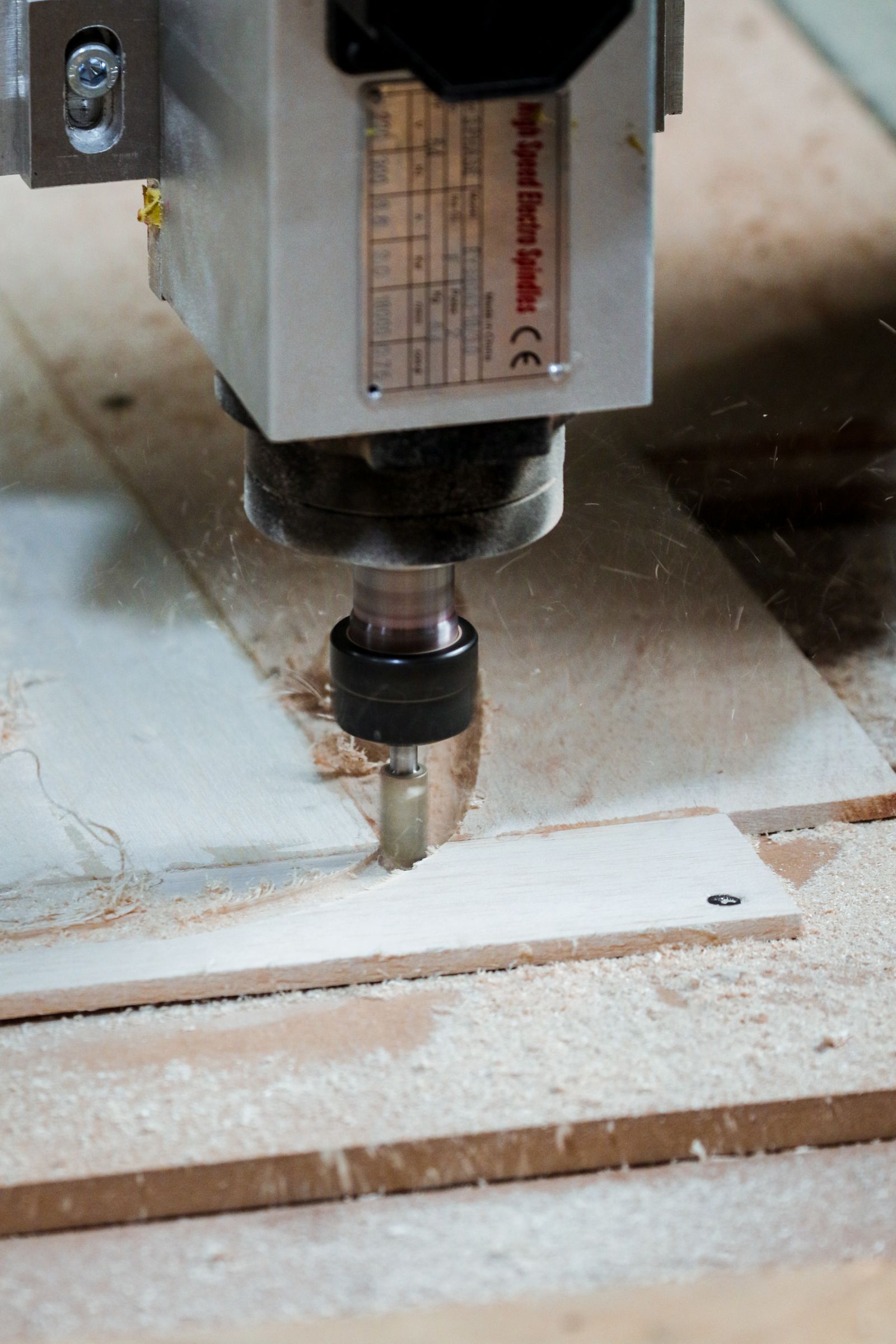
Common post-machining finishes include anodizing, bead blasting, powder coating, plating, passivation, polishing, and laser marking. The finish must be considered if it affects critical hole sizes or fits.
Key Process Parameters
The values below describe the typical operating envelope of our 4-axis milling cells. The fourth axis is used either as an indexing trunnion (A/C axis) or as a continuous rotary table; the actual configuration is selected to match the part.
Parameter | Typical Value |
|---|---|
Axis configuration | 3 linear (X / Y / Z) + 1 rotary (A or B); trunnion or horizontal rotary table |
Rotary table diameter | 200 – 320 mm standard; up to 500 mm available |
Rotary index accuracy | ±0.01— indexing; ±5 arc-sec on higher-end tables |
Standard linear tolerance | ±0.05 mm; ±0.025 mm on critical features; ±0.01 mm by review |
Surface finish (as-machined) | Ra 1.6 – 3.2 µm typical; Ra 0.8 µm on finishing passes |
Maximum part envelope | Up to 800 — 500 — 450 mm on table; subject to part swing diameter |
Batch range | 1 to 5,000+ pieces |
Lead time | Prototypes 5–7 business days; production 10–20 business days |
Accepted CAD formats | STEP, IGES, X_T, SLDPRT, DXF, DWG, PDF |
Machine platforms | 4-axis VMC with integrated trunnion, 12,000–20,000 rpm spindle |
Surface Finish Options
- As-machined — Ra 1.6 – 3.2 µm, standard mill finish
- Bead blast — glass bead or aluminum oxide, matte cosmetic finish
- Anodize Type II — clear or dyed, 5–25 µm coating, decorative / corrosion
- Hard anodize Type III — 25–75 µm, wear- and corrosion-resistant
- Powder coat — polyester, epoxy, hybrid, custom color
- Liquid painting — primer + topcoat systems
- Electroplating — nickel, tin, zinc, gold, silver
- Passivation — ASTM A967 / AMS 2700 for stainless steel
- Black oxide — MIL-DTL-13924, mild corrosion resistance
- Polishing & electropolishing — for stainless cosmetic or sanitary parts
- Laser marking & engraving — part numbers, logos, UID codes
Design Considerations (DFM Tips)
- Use the rotary axis for what it is best at — drilling radial holes, milling faces around a cylinder, or wrapping features that would otherwise need multiple setups.
- Internal corner radii — keep — end-mill radius; R — 1.0 mm preferred.
- Standard hole sizes — avoid odd-numbered diameters that force boring or EDM.
- Wall thickness — maintain — 1.0 mm in aluminum, — 0.8 mm in plastics; thin walls deflect under cutter force.
- Specify the rotary datum — call out the centerline of the rotation as a datum and reference radial features back to it.
- Indexing vs. simultaneous — choose indexing when features are on flat angular faces; use simultaneous 4-axis only when the surface truly benefits.
- Workholding access — confirm that the chuck, fixture, or vacuum plate does not collide with the cutting tool at any programmed angle.
- Swing envelope — keep features within the machine's swing diameter to avoid re-fixturing.
- Tolerance strategy — tighten tolerances on features that align across angles; loosen them on cosmetic faces.
What angular accuracy can you hold?
±0.05— is typical; ±0.01— is achievable on selected features with calibrated rotary axes, smaller cutters, and slower finishing passes. Tight angular tolerance is verified on a CMM, not a protractor.
Common Defects & Prevention
4-axis defects often come from angular misalignment, workholding shift, or interaction between the linear and rotary axes. The list below covers the failure modes we see most often, with prevention steps.
Defect | Cause | Prevention |
|---|---|---|
Angular position error | Backlash in the rotary axis, indexing drift, or thermal change on the trunnion | Use direct-drive or dual-pinion rotary table, calibrate periodically, allow thermal stabilization, verify with a probe |
Concentricity / runout drift | Re-clamping between setups, chuck contamination, worn collet | Single-setup machining wherever possible, clean chuck, replace collets on schedule, verified datum alignment |
Chatter on wrap-around features | Long tool stick-out, excessive radial engagement, harmonic resonance between spindle and table | Reduce stick-out, lower radial depth-of-cut, switch to trochoidal toolpath, balance spindle speed to avoid resonance |
Workholding slip / shift | Insufficient clamping force, lifting moment during heavy cuts, soft-jaw mismatch | Match soft jaws to the part, verify torque on fixture screws, use loc-pin + clamp combo, confirm no lift before roughing |
Surface mismatch across indexed faces | Different cutter lengths, varying step-over, indexed faces not aligned to the same datum | Use a single tool for matched finishes, define a master datum, hold tight indexer accuracy, document tool assignments per face |
Tool collision on rotary moves | Tool, holder, or fixture swing into a fixed obstacle during index | Simulate the full index range in CAM with collision detection, check swing diameter, use the shortest possible tool |
Chip evacuation on radial features | Chips pack in the bottom of a wrap-around pocket, re-cut and damage the surface | Through-spindle coolant, air blast, retract-and-clear cycles, choice of cutter with chip-breaking geometry |
Burr formation on edge transitions | Exit-side tear on indexed faces, sharp grain in aluminum and stainless | Sharp cutter, proper exit ramp, light edge-break on every face, tumble or hand-deburr as a controlled operation |
Comparison With Related Processes
4-axis sits between standard 3-axis milling and full 5-axis simultaneous work. The table below clarifies when 4-axis is the right choice over the alternatives.
Aspect | 4-Axis Milling (this process) | 3-Axis Milling | 5-Axis Simultaneous Milling |
|---|---|---|---|
Ideal geometry | Multi-face prismatic parts, radial holes, indexed features on cylindrical or cubic blanks | Single-face or 3-face prismatic features; flat plates, brackets, housings | Compound angles, sculpted freeform surfaces, undercuts, single-setup complex parts |
Setups per part | 1 – 2 (rotary axis replaces a re-clamp) | 2 – 4 (each re-clamp is a setup) | 1 (single setup for the entire part) |
Tightest tolerance | ±0.01 mm linear; ±0.01— angular | ±0.01 mm linear; angular tolerance limited by re-clamp | ±0.01 mm linear; ±0.005— angular; 0.02 mm profile on freeform |
Cost vs. this process | Baseline (middle cost tier) | Lower for parts that don't need the rotary axis | + 30 – 80 % programming and cycle time |
When to choose | Multi-face parts where features on different faces need to align; radial drilled holes; mid-volume production of indexed parts | Simple prismatic parts; cost-sensitive single-face geometry; prototypes | Sculpted surfaces, compound angles, undercuts, single-setup high-value parts |
Industry Standards & Certifications
The standards below apply to 4-axis work in particular and to CNC machining in general. Customer-required certifications are referenced in the project scope and documented accordingly.
- ISO 9001:2015 — quality management system baseline.
- AS9100D / AS9102 — aerospace quality management; FAI report format.
- ISO 13485:2016 — medical device QMS, applicable to medical and life-sciences parts.
- IATF 16949 — automotive QMS, with PPAP, APQP, and control plan requirements.
- ISO 2768 — general tolerances (medium / fine / very fine classes).
- ASME Y14.5-2018 — GD&T standard, including datum scheme and feature control frames.
- ISO 5459 — datums and datum systems for geometric specification.
- ISO 1101 — geometrical product specifications, including orientation and run-out.
- VDI 2230 — bolted joint calculation, relevant for fastener and boss features.
- ASTM A967 / AMS 2700 — passivation of stainless steel.
- MIL-DTL-13924 — black oxide coating.
- MIL-A-8625 — anodize Type II / Type III on aluminum.
- RoHS / REACH — substance compliance for European market access.
- ITAR / EAR — controlled technical data and export compliance for defense parts.
Packaging, Shipping & Documentation
Packaging protects machined features, threads, and precision surfaces during transit. The level of packaging scales with part size, value, and shipping method; documentation is enclosed per customer requirement.
Related Capabilities & Cross-Services
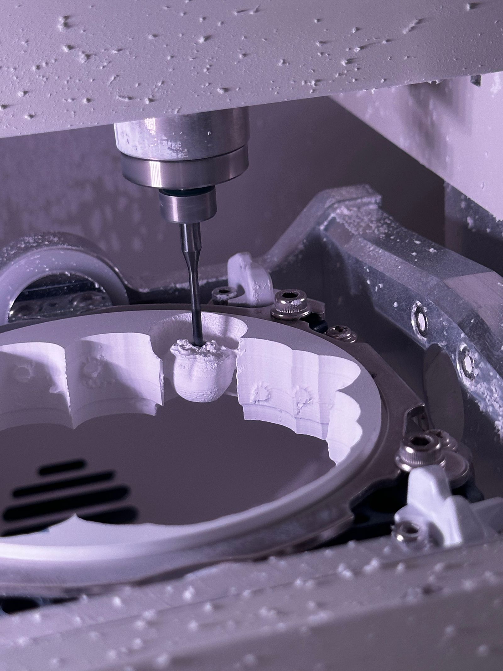
4-axis milling is often one step in a longer workflow. We coordinate the surrounding services so customers get a single point of accountability for the entire part, not a list of subcontractors.
- Post-machining finishing — bead blast, tumble, hand deburr, light polishing, edge-break, and cosmetic buffing in-house.
- Anodizing & plating — Type II / Type III anodize, electroless nickel, zinc, tin, gold, and silver plating through qualified partners.
- Powder coat & wet painting — polyester, epoxy, hybrid systems, RAL / Pantone color matching, primer + topcoat, and clear coat.
- Heat treatment — through-hardening, case hardening, tempering, solution treatment, and aging (17-4 PH H900 / H1025 / H1075, 4140 QT, etc.).
- Threading & thread inspection — internal / external thread milling, thread gauges, and SPC thread inspection on request.
- Light assembly & kitting — fastener installation, insert pressing, sub-assembly, and kit packaging.
- Laser marking & engraving — part numbers, logos, UID, 2D Data Matrix, and traceability codes.
- Design for manufacturing (DFM) review — feedback on datums, tolerances, and rotary-axis features before cutting chips.
- CMM inspection & 3D scanning — full GD&T verification with rotary datum alignment and CAD-comparison for complex geometry.
- Subcontracted services coordination — single point of contact for heat-treat, plating, anodize, and coating partners.
- Manifolds
- Multi-side fixtures
- Connector bodies
- Radial feature components
Features and Typical Components
Well-suited features include bolt circles, cross holes, indexed pockets, flats on shafts, curved grooves, external profiles around a cylindrical body, and repeated angular patterns.
Typical components:Typical components include rotary fixtures, flanges, housings with radial interfaces, shafts with milled flats, valve components, sensor bodies, and custom automation parts.
Advantages and Applications
Industries & Applications
- Aerospace & defense — manifold blocks, hydraulic fittings, sensor-mount brackets, prototype airframe parts
- Automotive — prototype transmission housings, intake components, EV motor brackets, sensor mounts
- Fluid power & hydraulics — valve bodies, manifold blocks, pump housings, custom fittings
- Medical devices — instrument handles, imaging-system components, prototype surgical-tool bodies
- Robotics & automation — rotary indexing tables, gear-housing prototypes, multi-face gripper components
- Industrial machinery — bearing housings, gear blanks, connector bodies, fixture bases
- Energy — wind-turbine prototype hardware, oil & gas sub-assembly blocks, solar tracker components
How is the 4-axis inspected?
Final inspection uses a CMM with the rotary datum aligned to machine coordinates. Angular features are checked against their callouts, and the final report documents the actual measured values, not just pass/fail.
Manufacturing Considerations
The design should establish a stable rotary datum and identify the angular relationship between all critical features. Workholding, tool reach, part balance, and access to the clamped face should be reviewed before choosing the machining route.
Can you machine a complete part in one 4-axis setup?
Often yes, especially when the part is symmetric about a centerline. For parts that still need opposite-side features, a second op on a 3-axis or turn-mill cell is planned and quoted explicitly.
Cost Drivers & Lead Time Factors
Adding a 4th axis typically improves accuracy and reduces setups, but it also adds programming and fixturing cost. The variables below are what most influence the final quote.

