

Plasma-Cut Fabrication Context
Typical parts include structural plate components, equipment frames, guards, brackets, base plates, repair parts, industrial machinery components, and welded fabrication assemblies.
Frequently Asked Questions
Process | Ionized gas arc on electrically conductive material |
|---|---|
Typical materials | Carbon steel, stainless, aluminum plate, structural steel |
Edge consideration | Dross, taper, heat-affected zone, distortion |
Source review | 2D profile, material, thickness, weld or bend information, and quantity |
Ionized Arc and Conductive Plate
Plasma cutting uses a high-temperature ionized gas arc to cut electrically conductive material. It is a thermal cutting process that can be programmed for profiles, holes, slots, and plate components, often followed by edge preparation, welding, machining, or coating depending on the application.
Process route
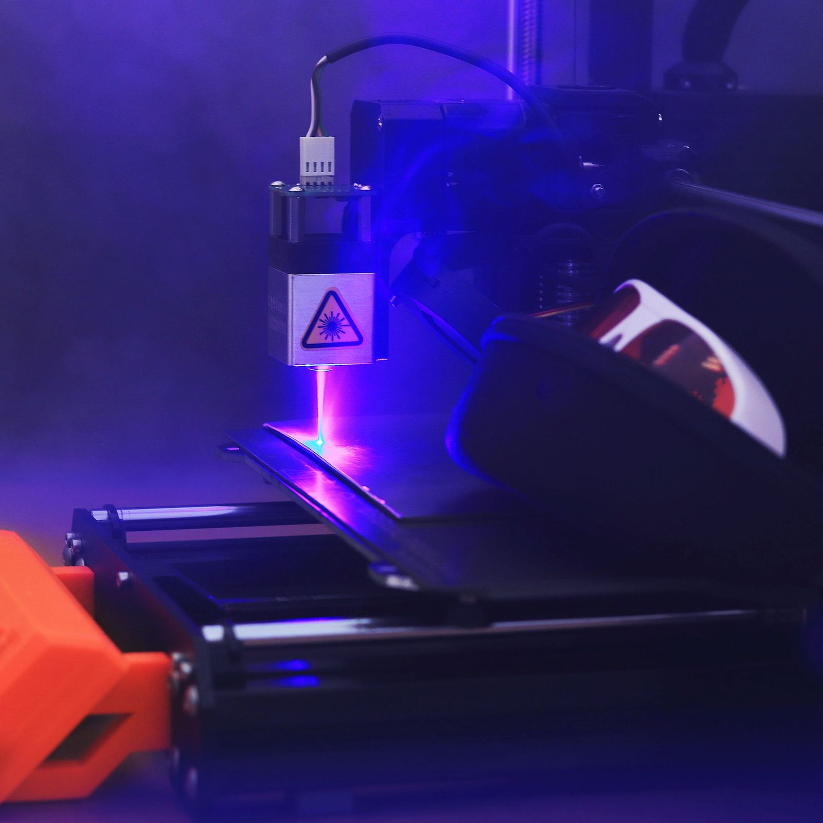
The route reviews conductive material and thickness, nesting, pierce and cut order, cut-quality requirement, dross removal, edge preparation, flatness, and the secondary fabrication steps that will follow the cut.
Design input | Why it changes the outcome |
|---|---|
Material and thickness | Plasma cutting is limited to conductive materials. Material grade, thickness, surface condition, and intended weld or coating process should be supplied with the drawing. |
Profile and small features | Typical features include plate profiles, mounting holes, slots, machine bases, structural components, gussets, brackets, flanges, and fabrication blanks. |
Downstream operation | Bending, welding, machining, coating, and assembly can change the most suitable cutting route. |
Inspection and acceptance
Quality checks commonly consider the profile, hole/slot location, edge taper, dross, heat-affected area, distortion, and readiness for the downstream fabrication or assembly process.
Important: A profile may meet its nominal 2D dimensions and still need a defined plan for burr, taper, heat effect, flatness, protective film, or later edge preparation.
When Plasma Fits the Job
Choose plasma for conductive-material plate work where its cutting characteristics fit the required outcome. Laser can suit finer sheet profiles; waterjet is useful when avoiding a heat-affected zone is important.
RFQ details
Provide a 2D profile, material details, thickness, critical dimensions, edge preparation, dross allowance, flatness expectations, weld symbols or bend information, and target quantity.
Quote check: Provide a flat pattern, material grade, thickness, quantity, critical dimensions, edge expectation, and all required secondary operations.
Key Process Parameters
Plasma cutting is selected when electrically conductive plate or sheet must be profiled quickly, when a beveled edge is required for weld preparation, and when the heat-affected zone can be planned into the downstream process. The values below are typical for a CNC table plasma system; specific cut quality is reviewed against the supplied profile and material.
Parameter | Typical Value |
|---|---|
Material thickness (mild steel) | 0.5 mm to 25 mm production; up to 50 mm with edge-quality review |
Material thickness (stainless) | 0.5 mm to 30 mm |
Material thickness (aluminum) | 0.5 mm to 25 mm |
Dimensional tolerance | ±0.5 mm typical, ±0.2 mm achievable on thin gauge with fine cut |
Minimum hole diameter | Approximately 1.5× material thickness (production cut) |
Maximum plate size | Up to 2 m × 6 m table envelope (subject to nesting) |
Edge bevel | 45° weld prep available on plate thicknesses from about 6 mm and up |
Kerf width | Approximately 1.0 mm to 1.6 mm depending on amperage and material |
Heat-affected zone (HAZ) | Approximately 0.5 mm to 2.0 mm per side, depending on material and speed |
Batch range | 1 prototype part to several hundred pieces per release |
Lead time | 1–3 working days for prototypes; 5–15 working days for production runs |
Accepted file formats | DXF, DWG, STEP (2D profile preferred), and PDF drawing |
Equipment used | CNC plasma table with high-frequency starting torch and downdraft fume extraction |
Materials We Cut
Plasma cutting requires an electrically conductive workpiece. The list below shows the materials and grade examples most commonly processed on our table.
- Mild and carbon steel — ASTM A36, A572 Gr.50, A516 Gr.70, 1018, 1020, S235JR, S355JR
- Hot-rolled plate — A36 HR, SS400, S275JR, S355JR
- Cold-rolled sheet — CR1008, DC01 in gauges up to about 3 mm
- Stainless steel — 304 / 304L, 316 / 316L, 321, 430, 3CR12
- Galvanized steel — G90, G60, hot-dip galvanized sheet and plate
- Aluminum plate — 5052, 5083, 6061, 3003, 1100 series
- Copper and brass plate — C110, C260 (Cartridge brass), C360 (free-machining)
- Electrical steel and silicon steel — M19, M36, and similar lamination grades
- Wear and abrasion-resistant plate — AR400, AR500 (with review of edge quality)
- High-strength low-alloy — A514, Hardox® 400/450 (with speed and amperage review)
Standard Tolerances & Achievable Precision
Plasma tolerance is controlled by cut parameter, material thickness, table condition, and nesting. Edge taper, dross, and HAZ are part of the process and should be planned for in the design.
- Outer profile tolerance: ±0.5 mm standard on plate up to 12 mm, ±0.8 mm on plate above 12 mm
- Hole and slot tolerance: ±0.3 mm achievable on thin gauge with fine-cut parameters
- Edge taper: up to approximately 1°–3° depending on thickness and speed
- ISO 2768-m used as default general tolerance where drawing is silent
- Functional dimensions that must be held tighter should be finish-machined after cutting
- Dimensional review is performed against the supplied 2D drawing before release
Quality Control & Inspection
Plasma parts are checked against the supplied 2D profile and any listed critical dimensions. Inspection reports can be released with the shipment on request.
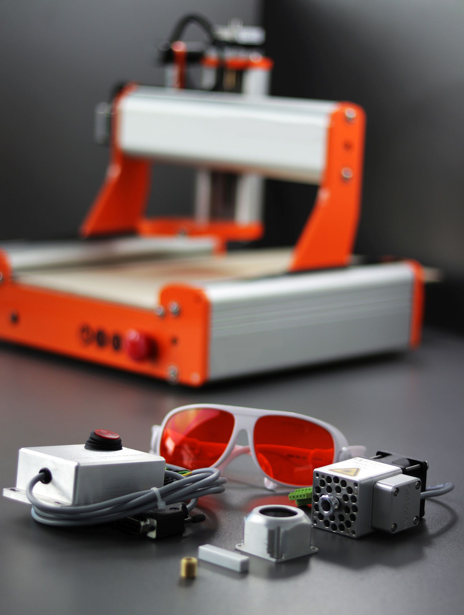
- First-article inspection against the supplied DXF or PDF drawing
- In-process visual check of pierce quality, dross, and kerf
- Final dimensional check using calipers, height gauges, tape measures, and templates
- Visual inspection of edge condition, taper, and heat tint
- Optional CMM verification on tight-tolerance features
- Surface roughness comparison against an approved reference where specified
- Material certificate (mill cert) review for traceable plate
- Inspection report or first-article layout available on request
Design Considerations (DFM Tips)
- Keep the smallest internal hole diameter at least 1.5× the material thickness for clean cut
- Avoid sharp inside corners; use a radius of at least the material thickness where possible
- Locate critical dimensions away from the cut edge so they can be finish-machined if needed
- Indicate which edges require dross removal, grinding, or weld prep directly on the drawing
- Specify a flat pattern with grain direction when the plate will be formed or rolled after cut
- Allow ≥ material thickness between adjacent slots and holes to limit heat distortion
- Mark protective film, paper, or paint backing on the cut face if the part must stay flat
- For welded assemblies, indicate bevel direction, root face, and whether the cut is weld-ready
- For galvanizing after cut, leave sufficient drain and vent holes on enclosed profiles
- Group parts in the same material and thickness to reduce setup and material cost
Industries & Applications
Plasma-cut plate and sheet are common in industries where a conductive part is profiled, formed, welded, or finished before entering a larger product.
- Agricultural and construction equipment — wear plates, brackets, guards, attachment components
- Industrial machinery — machine bases, side panels, covers, frames
- Material handling — conveyor components, chute liners, transition plates
- Energy and power — electrical enclosures, switchgear panels, transformer components
- Automotive and transport — truck and trailer plates, brackets, structural inserts
- Architectural and structural steel — base plates, gussets, stair treads, custom profiles
- Heavy equipment and mining — cutting edges, wear liners, screen plates
- General fabrication and repair — spare parts, replacement panels, custom blanks
How is dross handled on the cut edge?
Dross is a normal by-product of plasma cutting. It can be removed by grinding, sanding, or shot blasting depending on the material and the next operation. Cut parameters are selected to minimize dross where the application requires it.
What file should be provided for cutting?
A 2D DXF or DWG of the flat pattern is preferred. A PDF drawing with all critical dimensions, the material grade, thickness, and any required edge preparation is also accepted.
How to Get a Quote
Send a 2D DXF or DWG, a PDF drawing with tolerances and weld prep notes, the material grade and thickness, the required quantity, the edge condition, and any secondary operations such as bending, welding, machining, coating, or hardware. The reply includes a DFM review of the profile (holes, slots, grain, bevels), a confirmed lead time, and a unit price. Material cert and inspection report are available on request.
Process Flow & Manufacturing Sequence
A CNC plasma cut begins with verified stock and a nested cut plan, and ends with an edge-conditioned, inspected, and labeled part. The sequence below describes the operations from plate receipt to packed shipment, and is the working flow used for every plasma release.
- Drawing and file review — receive 2D DXF/DWG or PDF drawing; confirm material grade, thickness, profile geometry, bevel direction, hole and slot sizes, and any critical dimensions.
- Nesting and cut-program preparation — build a nest on the supplied plate size to maximize material yield; assign lead-in / lead-out, pierce points, cut order, and cut parameters (amperage, voltage, speed, gas) per feature.
- Plate receipt and identification — verify heat lot, plate certificate (EN 10204 3.1 where applicable), thickness, surface condition, and dimensional check against the order before loading the table.
- Table setup and squaring — load plate on the downdraft table, square to the machine datum, set Z-axis standoff (typically 1.5–3 mm above the plate depending on the torch), and confirm ground clamp contact.
- Torch and consumable selection — install electrode, swirl ring, retaining cap, and nozzle sized for the chosen amperage and material; verify torch alignment and swirl-blower condition.
- Pierce and cut execution — pierce on a lead-in path to keep the pierce bead off the finished edge; traverse at programmed speed; the CNC controls arc voltage height for consistent standoff on thin plate.
- In-process dross and quality check — the operator inspects pierce quality, dross level, kerf, and edge taper on the first part and at interval cuts; parameters are adjusted if drift is observed.
- Slag and dross removal — chip or grind dross from the lower edge; for weld-prep edges, grind to the specified root face and angle.
- Edge finishing — chamfer, bevel, deburr sharp corners, or radius as called on the drawing; for cosmetic parts, bead blast or wire brush the heat tint.
- Flatness and stress relief — check flatness; if distortion is beyond drawing tolerance, the part is rolled or pressed flat, or a stress-relief cycle is added before further fabrication.
- Inspection — measure critical features against the 2D drawing, record the layout, attach photo evidence where required, and stamp the traveler.
- Marking, kitting, and packaging — apply part number, revision, or heat-lot mark per the customer specification; bag, label, and pack with foam, VCI paper, or crating as required.
Material Property Reference
The table below lists typical material properties for the conductive plate and sheet grades most often processed on a CNC plasma table. Values are industry references and are confirmed against the supplied mill certificate when one is provided.
Material | Density (g/cm³) | Tensile Strength (MPa) | Yield Strength (MPa) | Hardness (HB) | Machinability Rating (%) |
|---|---|---|---|---|---|
Mild steel A36 | 7.85 | 400–550 | 250 | 119–159 | 70 |
Carbon steel 1018 | 7.87 | 440 | 370 | 131 | 70 |
HSLA A572 Gr.50 | 7.85 | 450 | 345 | 135 | 60 |
Pressure vessel A516 Gr.70 | 7.85 | 485–620 | 260 | 130–170 | 55 |
Stainless 304 / 304L | 8.00 | 515–620 | 205–310 | 150–180 | 45 |
Stainless 316 / 316L | 8.00 | 515–620 | 220–310 | 150–180 | 45 |
Aluminum 5052 | 2.68 | 210–260 | 130–193 | 60–75 | 200 |
Aluminum 6061 | 2.70 | 290 | 240 | 95 | 180 |
Galvanized steel G90 | 7.85 | 365–480 | 230–345 | 120–150 | 65 |
AR400 abrasion-resistant | 7.85 | 1250 | 1000 | 360–440 | 25 |
Copper C110 | 8.96 | 220–330 | 70–330 | 45–65 | 20 |
Brass C260 | 8.53 | 330–540 | 130–400 | 55–110 | 30 |
Cost Drivers & Lead Time Factors
Plasma cutting cost is driven mainly by material grade and thickness, plate utilization, pierce count, cut length, edge quality, and any secondary operations such as dross removal, bevel, machining, bending, or coating. Lead time is driven by plate sourcing, programming and nesting effort, the secondary operation queue, and inspection scope. The table below summarizes typical lead times by scenario; an exact lead time is quoted against the drawing.
Scenario | Typical Lead Time | Main Driver |
|---|---|---|
Single prototype from stock plate, no finishing | 1–3 working days | Programming and nesting |
Prototype with dross removal and edge grind | 3–5 working days | Secondary labor capacity |
Weld-prep bevel on 6–25 mm plate | 5–10 working days | Bevel setup and edge grinding |
Production run 50–200 parts, one material and thickness | 5–10 working days | Plate sourcing, cut time, and inspection |
Production run with bending, machining, or coating | 10–20 working days | Subcontractor queue and inspection |
Large plate with NDT, FAI, and MTC documentation | 15–25 working days | Documentation scope and lab turnaround |
Common Defects & Prevention
Plasma cutting has known characteristic defects. The table below lists the defects seen most often on a CNC plasma table, the cause, and the prevention step applied during production.
Defect | Cause | Prevention |
|---|---|---|
Dross (low-side or high-side) | Incorrect speed, amperage, or standoff for material and thickness | Tune parameters per cut chart; verify on first pierce; grind if required |
Excessive heat-affected zone (HAZ) | Slow cut or high amperage on thin plate | Use fine-cut parameters on gauge material; review HAZ on stainless |
Edge taper (positive or negative) | Drift in arc voltage or worn nozzle; off-axis torch | Replace consumables on schedule; recalibrate height control |
Kerf variation across the cut | Inconsistent standoff or warped plate | Use arc-voltage height control; level plate on the table |
Slag adhesion at pierce point | Pierce too close to finished edge or insufficient lead-in | Place pierce off the finished edge; use a lead-in of 6–10 mm |
Warping or distortion | Uneven heat input, cut order, or thin plate under its own stress | Use balanced cut order, cut thin gauges with water pan, finish-flat where required |
Hole taper or undersized hole | Hole diameter < 1.5× plate thickness or incorrect parameters | Apply minimum hole rule; use fine-cut on small features |
Stainless discoloration / oxidation | Heat tint and oxygen exposure near the cut | Use nitrogen or argon-hydrogen shielding on stainless; passivate after cut |
Comparison With Related Processes
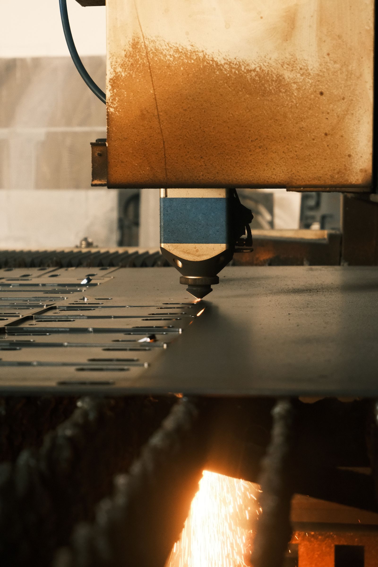
Plasma sits between laser and waterjet in capability. The table below compares plasma to the two processes most often considered alongside it, and to oxy-fuel for plate work.
Aspect | Plasma | Laser (Fiber / CO₂) | Waterjet |
|---|---|---|---|
Best thickness range (steel) | 3–25 mm production, up to 50 mm review | 0.5–15 mm | 3–100 mm+ |
Tolerance | ±0.5 mm typical | ±0.1 mm or better | ±0.1 mm or better |
HAZ | Yes, 0.5–2.0 mm per side | Yes, smaller (0.1–0.5 mm) | None (cold process) |
Bevel / weld prep | 45° available from ~6 mm up | Limited, with 5-axis head | Limited, with 5-axis head |
Material compatibility | Conductive only | Mostly metals | Any material (metal, stone, composite, glass) |
Relative cost on 6–20 mm steel | Low | Medium to high | Medium to high |
When to choose plasma | Conductive plate, 3–25 mm, weld-prep edge, fast turn | Thin gauge, tight tolerance, low HAZ | Thick plate, no HAZ, exotic material |
Industry Standards & Certifications
- ISO 9001:2015 — quality management system baseline
- AS9100D — aerospace quality management, applied where the program calls for it
- ISO 13485:2016 — medical device QMS, applied to medical and laboratory parts
- IATF 16949 — automotive QMS, applied to automotive series production
- ISO 2768 (medium class, −m) — default general tolerance on drawings that do not specify otherwise
- ASME Y14.5 — GD&T callouts honored on drawings that use the standard
- ISO 5459 — datum system reference for parts with complex datums
- EN 1090 — structural and welded fabrication, where CE-marked components are produced
- AWS C5.1 / C5.2 — weld prep geometry when the part enters a welded assembly
- RoHS and REACH — material compliance for electrical and consumer products
- EN 10204 3.1 / 3.2 — mill certificate type supplied with the plate on request
Packaging, Shipping & Documentation
Plasma-cut parts are packaged to protect the cut edge from in-transit damage and to keep the cosmetic face clean. The list below describes the standard packaging, the available shipping options, and the documents that can be released with the shipment.
- Standard packaging — foam or corrugated sheet between layers, VCI paper for steel, plastic film or stretch wrap for plate bundles, individual bags for cosmetic or deburred parts, wooden crate for export or plate above 25 mm thickness.
- Edge protection — cardboard edge protectors, plastic corner caps, or foam profile on beveled or ground edges.
- Identification — part number, revision, quantity, and heat-lot label on the outside of each pack; bar code or QR label on request.
- Shipping options — parcel, LTL, full truckload, air freight, sea freight with or without DDP, customer-arranged carrier, and EXW / FOB / CIF terms.
- Standard documents — packing list, commercial invoice, Certificate of Conformance (C of C), Mill Test Certificate (MTC) where the material is traceable, and dimensional / first-article inspection report on request.
- Supplementary documents — photo record of the cut nest, weld-prep layout, plating or coating certificate, and country-of-origin declaration where required.
Related Capabilities & Cross-Services
Plasma-cut plate rarely ships as a finished product on its own. The capabilities below are typically paired with plasma to take a part from raw plate to a ready-to-install component or welded assembly.
- Laser cutting — for thin gauge and tight-tolerance features where HAZ must be minimized
- Waterjet cutting — for non-conductive material or where a no-HAZ edge is required
- CNC machining — facing, drilling, tapping, and tight-tolerance features after cut
- CNC bending and forming — brake press forming of brackets, panels, and weldments
- Welding — MIG / TIG / spot — welded assemblies from plasma-cut components
- Surface treatment — powder coat, wet paint, hot-dip galvanizing, zinc plating, anodizing on aluminum
- Grinding and deburring — edge conditioning and weld-prep bevel
- Hardware insertion — pressed-in nuts, studs, and PEM-type inserts after cut and form
- Assembly — kitting of plates, formed parts, hardware, and subassemblies into a finished unit
- Reverse engineering — legacy plate parts and discontinued spares rebuilt from a sample
Thermal Edge Preparation
Plan for dross removal, grinding, weld preparation, coating, and protection of dimensions that will be finish-machined after cutting.
Plasma cutting suits conductive plate work where its edge and thermal characteristics fit the downstream process.
Where the route adds value
Applications include industrial fabrication, structural components, heavy equipment, machine building, maintenance parts, transport equipment, and custom welded assemblies.
Question | Decision consequence |
|---|---|
Is heat effect acceptable? | Directs the choice between thermal and cold-cutting routes. |
Is the part finished after cutting? | Determines the needed edge condition and tolerance strategy. |
Will it be formed or welded? | Changes nesting, grain/film handling, and location of critical dimensions. |
Surface & Edge Finish Options
As-cut plasma leaves scale, dross, and a heat tint. The list below shows the finishes that can be applied to the cut edge or the cut face.
- As-cut (mill scale and dross present)
- Dross removal and edge grinding
- Bead blast / shot blast for paint preparation
- Edge chamfering or beveling (weld prep)
- Deburring of pierce points and sharp corners
- Wire brush for cosmetic cleanup
- Powder coat, wet paint, or primer after blasting
- Hot-dip galvanizing, zinc-rich primer, or zinc plating after cut
- Passivation on stainless steel edges after dross removal
- Protective film or paper applied to non-cut faces before processing
What is the maximum plate thickness for plasma cutting?
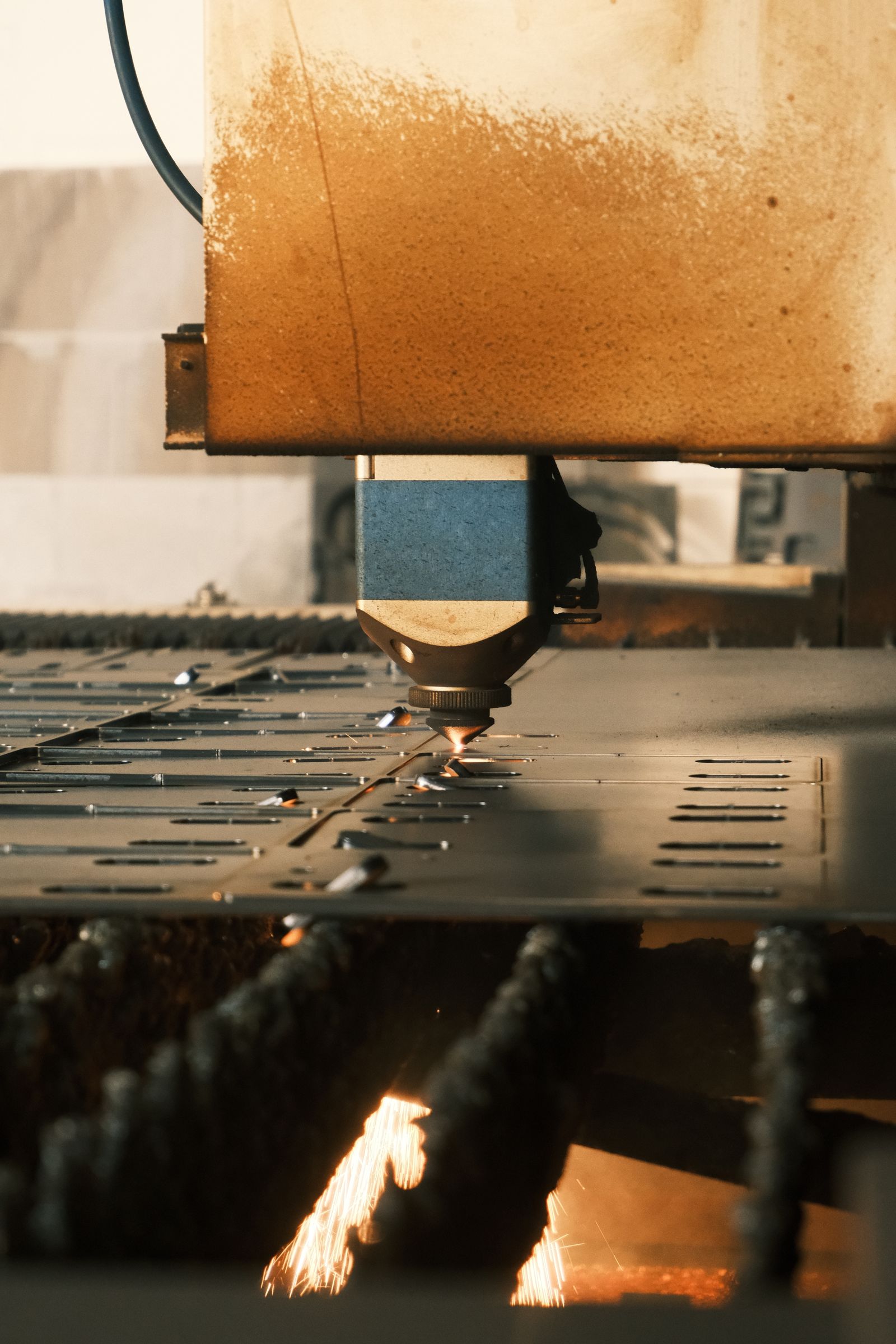
For production-quality edges, mild steel up to about 25 mm is routine. Plate above 25 mm and up to 50 mm can be cut with reduced edge quality and slower speeds; the application should be reviewed for dross, taper, and downstream finishing.
Is plasma cutting accurate enough for tight-tolerance holes?
Plasma is suitable for general profile and hole tolerance. For features that need to be held tighter than ±0.2 mm, the dimension is usually finish-machined after cutting, or a different process such as laser or waterjet is selected.
- Structural plate components
- Equipment frames and base plates
- Guards, gussets, and fabrication blanks
- Repair and maintenance parts
- Welded fabrication assemblies
Can plasma cut stainless steel and aluminum?
Yes. Stainless steel up to about 30 mm and aluminum up to about 25 mm are cut routinely. The edge will have a heat tint and may show dross, which can be removed by grinding or pickling depending on the application.
Does plasma cutting leave a heat-affected zone?
Yes. Plasma is a thermal process and the cut edge has a heat-affected zone. For parts that must avoid HAZ (for example, certain stainless or hardened applications), waterjet or laser cutting is reviewed instead.
—
—

