

Frequently Asked Questions
Do you grind both sides for parallelism?
Yes. For tight parallelism, the part is ground on one side, flipped on the magnetic chuck, and ground on the opposite side. The two faces are referenced to the same machine geometry so the parallelism is controlled.
What causes thermal distortion during grinding?
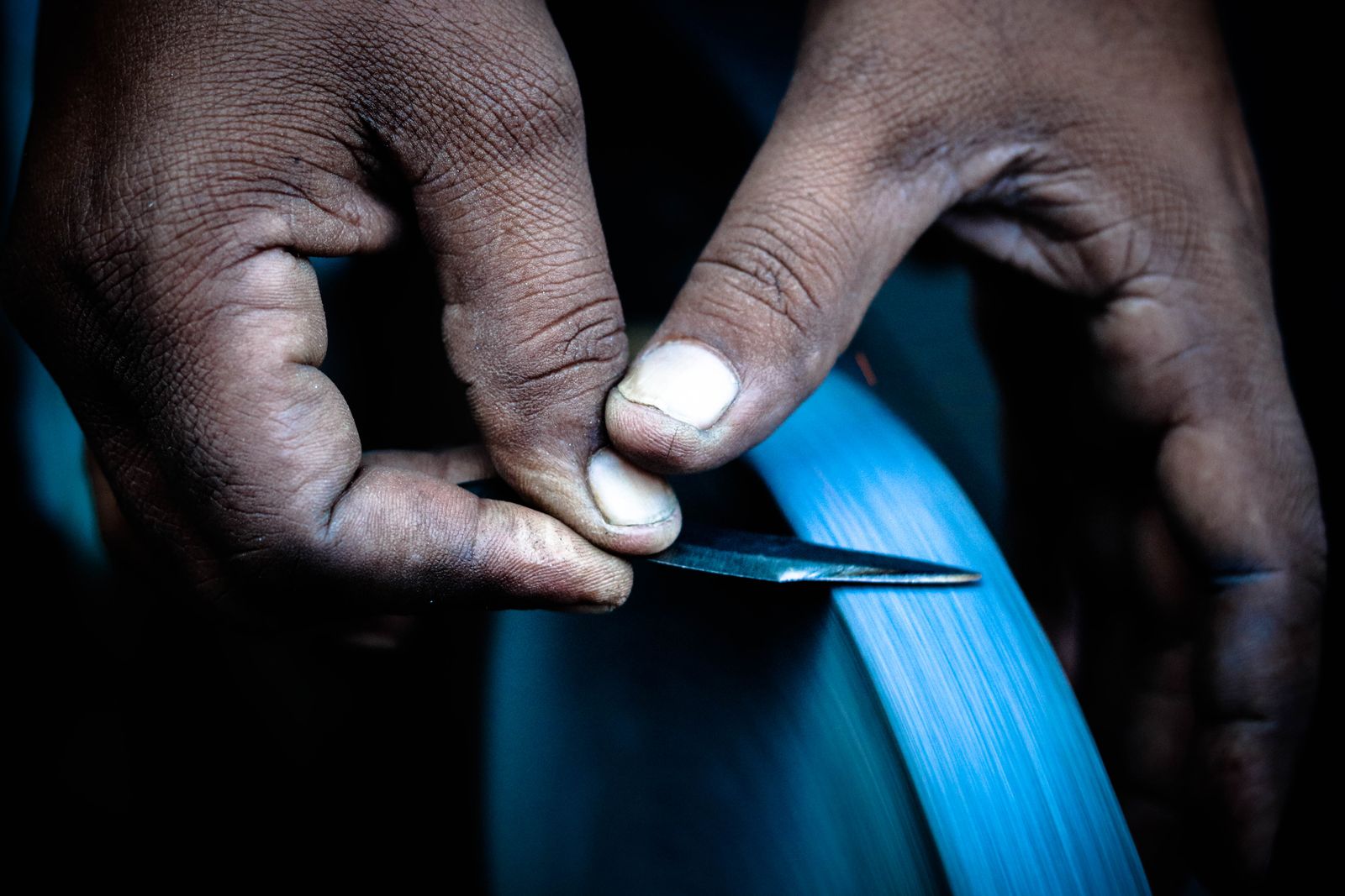
Most thermal drift comes from heat going into the workpiece from the cut and from a warm coolant supply. Long spark-out passes, an open coolant system at controlled temperature, and allowing the part to stabilise before final measurement are the standard controls.
Controlled feature | Flatness, parallelism, and surface finish |
|---|---|
Typical workpieces | Fixture plates, shims, wear plates, ground reference faces |
Workholding | Magnetic chuck, mechanical fixture, or dedicated clamping |
Source review | Drawing revision, material condition, and protected zones |
Flatness, Parallelism, and Stock Allowance
Surface grinding uses a rotating abrasive wheel to remove a controlled amount of material from a workpiece, most often to produce a flat, parallel, or precisely located surface. It is commonly used after milling or heat treatment when a functional face requires stable geometry, fine finish, or controlled thickness.
The Surface-Grinding Route
A typical plan establishes a stable magnetic, mechanical, or fixture-based hold, dresses the grinding wheel, rough-grinds toward the target size, and uses lighter finishing passes while monitoring heat and flatness. The exact sequence depends on material, hardness, stock allowance, and the relationship of the ground face to the part datums.
Before grinding | During grinding | After grinding |
|---|---|---|
Stock allowance, datums, stable support | Wheel condition, heat, passes, coolant, geometry checks | Deburr, protect, inspect, package |
PROCESS RISK: Heat, thin sections, interrupted surfaces, and unstable support can matter as much as nominal dimension.
Thermal Stability and Finish
Surface grinding may be applied to steels, stainless steels, tool steels, cast iron, aluminum, and selected hard materials. The workpiece material, hardness, wheel specification, and coolant plan must be evaluated together.
Finish and protection
The ground surface may be left functional as-machined or protected after cleaning. If plating, coating, or painting follows, define whether the ground surface must be masked or brought back to final size afterwards.
Question | Reason to resolve it before release |
|---|---|
Is the part heat treated? | Material condition can change wheel choice, stock allowance, and distortion risk. |
What edge condition is acceptable? | Functional edges, cosmetic faces, and assembly interfaces can require different deburring instructions. |
Measurement of Functional Faces
Inspection commonly considers thickness, flatness, parallelism, surface condition, edge break, and the relationship of the ground face to locating features. The measurement method should be capable of checking the requested geometric control.
Key Process Parameters
Parameter | Typical Value |
|---|---|
Grinding process | Horizontal-spindle surface grinding with reciprocating table; vertical-spindle on selected work |
Table size (typical machine) | 300 — 600 mm to 600 — 2,000 mm; larger envelope quoted per part |
Maximum workpiece height | Up to 400 mm under the wheel; larger parts on application |
Flatness | 0.005–0.020 mm over 300 mm; 0.01 mm / m on precision passes |
Parallelism | 0.01–0.03 mm between opposite faces on a given part |
Surface finish (Ra) | Ra 0.2–1.6 µm typical, depending on wheel grit, spark-out, and material |
Thickness tolerance | ±0.01 mm on shim and spacer work; ±0.025 mm standard |
Stock removal per pass | 0.005–0.05 mm on roughing; 0.001–0.005 mm on finishing / spark-out |
Wheel types | Aluminium-oxide, silicon-carbide, cubic-boron-nitride (CBN), and diamond wheels; selection by material |
Workholding | Permanent magnetic chuck, fine-pitch magnetic chuck, mechanical vice, or dedicated fixture |
Coolant | Water-soluble flood coolant; filtration and temperature control for thermal stability |
Batch range | Single-piece prototypes through 5,000-piece production runs |
Typical lead time | 3–7 working days prototypes; 7–20 working days production |
Accepted CAD formats | STEP, IGES, X_T, Parasolid, native SolidWorks / CATIA / NX / Fusion 360 |
Materials We Grind
- Carbon and alloy steels — 1018, 1045, 4140 pre-hard, 4340 Q&T, EN24, EN26, A36
- Tool and high-speed steels — A2, D2, O1, S7, H13, M2, M42, T1
- Stainless steels — 304 / 304L, 316 / 316L, 321, 410, 17-4PH, 15-5PH
- Bearing and through-hardened steels — 52100, case-hardened and induction-hardened components
- Cast iron and ductile iron — gray iron GG25, ductile iron 60-40-18, ADI grades
- Aluminum alloys — 6061-T6, 7075-T6, 2024-T3, MIC-6 cast plate
- Hardened alloys up to HRC 65 — including tool-steel die blocks and punches
- Engineering plastics and composites — phenolic, G10/FR4, PEEK, glass-fibre laminates
Quality Control & Inspection
Inspection is sized to the function of the ground face — sealing, sliding, or reference. For high-value or high-volume orders, in-process flatness checks are added between passes to catch drift before final dimensions are reached.
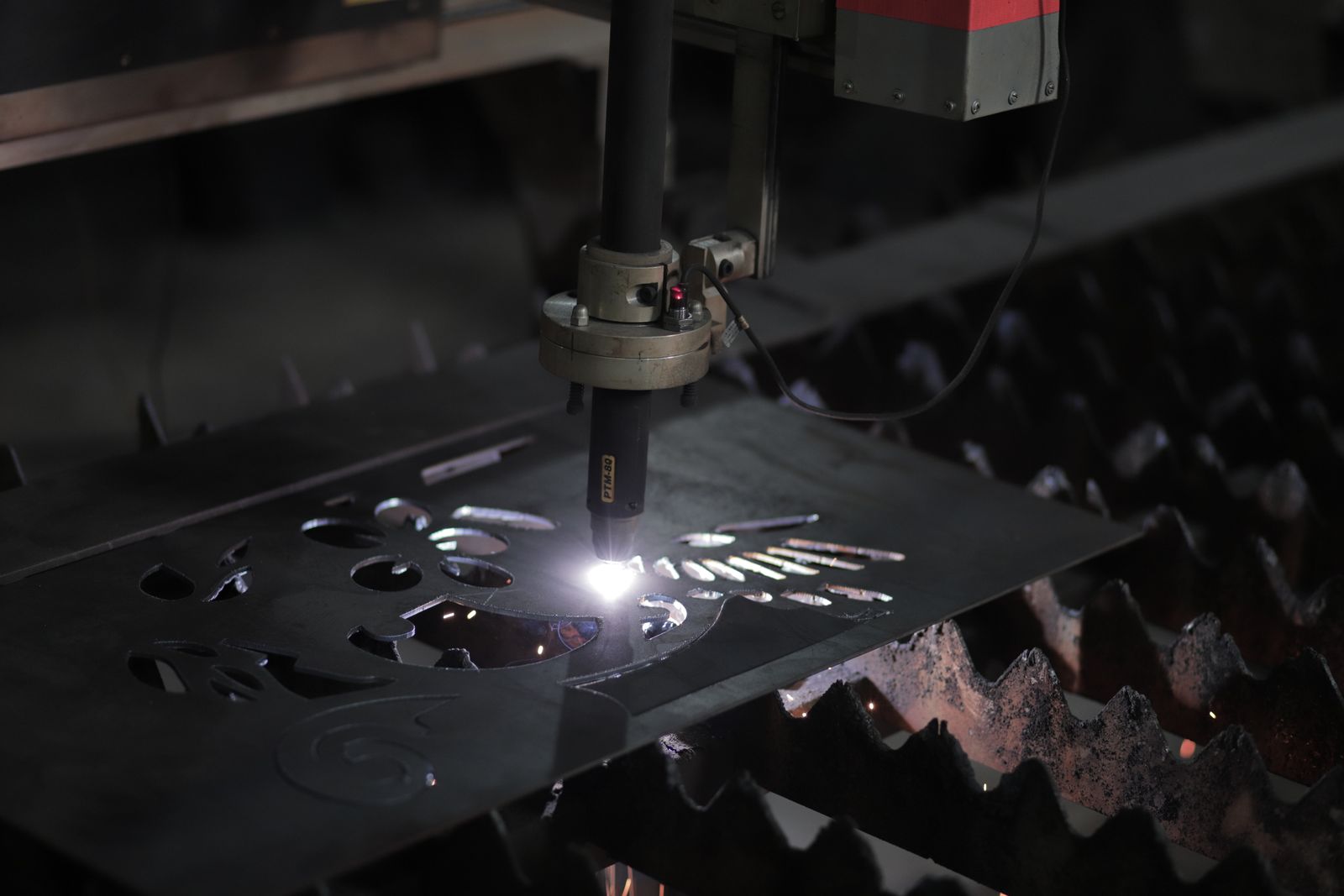
- CMM with a surface plate for flatness, parallelism, and datum reference verification
- Granite surface plate with dial test indicator for shop-floor flatness checks
- Surface roughness tester (profilometer) for Ra on the ground face
- Hardness tester (Rockwell / Vickers / Brinell) for hardened or through-hardened parts
- Digital micrometers, calipers, and depth gauges for thickness and feature dimensions
- First-article inspection against the full drawing; in-process checks between rough and finish passes
- Final inspection report and material certification (EN 10204 3.1) on request
What is the difference between surface grinding and milling a flat face?
Surface grinding uses an abrasive wheel to remove a controlled, very small amount of material. It produces tighter flatness, parallelism, and finer surface finish than milling, especially on hardened parts where milling is not practical.
What flatness can be held?
Routine work holds 0.005–0.020 mm over 300 mm. On precision passes with spark-out, flatness of 0.005 mm over 300 mm is achievable on rigid parts. The exact result depends on the material, the part geometry, and the fixture.
How to Get a Quote
Send the 3D model and 2D drawing with GD&T, the material grade and condition (including hardness for hardened parts), the order quantity, surface-finish expectations, and any inspection requirements. For very tight flatness or thin parts, mention the source of the blank (milled, saw-cut, waterjet) so the right starting strategy is set.
Within one working day you receive a written quote with DFM feedback, the proposed grinding and inspection route, lead time, and unit price. Where spark-out passes, a light lap, or an alternative wheel can deliver the same result at lower cost, it is called out in the quote.
Process Flow & Manufacturing Sequence
Surface grinding is a finishing operation. It is scheduled after rough machining, after heat treatment (when specified), and after the part has been stress-relieved. The route below covers a typical horizontal-spindle surface-grind cycle from a milled or saw-cut blank to an inspected, packaged face.
- Drawing review and datum selection — confirm the primary ground datum, the flatness / parallelism requirements, the Ra target, the part envelope, and any zones that must remain unground.
- Heat treatment (if required) — through-hardening, case-hardening, or ageing is performed before grinding; the pre-grind hardness is verified so the wheel and parameters are matched to the material.
- Stress relief — heavy milling and heat treatment introduce residual stress; a stress-relief cycle stabilises the part before the finish grind.
- Stock preparation — the blank is faced, edged, or pre-milled to bring the part close to the final thickness with even stock on both sides; thin parts are pre-machined flat to control distortion.
- Workholding selection — permanent magnetic chuck for general steel and iron parts, fine-pitch magnetic chuck for thin parts, mechanical vice for non-magnetic materials, or dedicated fixture for complex shapes.
- Wheel selection and dressing — aluminium-oxide, silicon-carbide, CBN, or diamond wheel is selected by material; the wheel is dressed to a true profile before the cut.
- Rough grinding — heavy stock is removed with deeper passes to bring the part close to the target thickness; parameters are chosen to keep heat input low and avoid thermal distortion.
- Intermediate check — thickness, flatness, and parallelism are checked on a granite plate with a DTI before final passes to confirm the part is on the right trajectory.
- Finish grinding and spark-out — light cuts with a sharp, fine-grit wheel and several spark-out passes at the end of the table stroke bring the surface to the print's flatness, parallelism, and Ra target.
- Flip and grind back (when required) — for tight parallelism, the part is flipped on the magnetic chuck and the second face is ground; the two sides reference the same machine geometry.
- Deburring and edge break — external edges of the ground face are chamfered or edge-broken to print specification to prevent handling damage and burrs.
- Cleaning, protection, and inspection — the part is washed, protected with light oil, VCI, or wax if specified, and inspected against the full print.
Material Property Reference
Material | Density (g/cm?) | Tensile Strength (MPa) | Yield Strength (MPa) | Hardness (HB) | Machinability (%) |
|---|---|---|---|---|---|
Steel 1018 (cold-drawn) | 7.87 | 440 | 370 | 130 | 70 |
Steel 4140 pre-hard (HRC 28–32) | 7.85 | 1,020 | 900 | 290 | 55 |
Tool steel D2 (hardened, HRC 58–62) | 7.70 | 1,760 | 1,500 | 580 | 25 |
Tool steel H13 (hardened, HRC 50–54) | 7.80 | 1,510 | 1,380 | 500 | 30 |
Tool steel A2 (hardened, HRC 60–62) | 7.86 | 1,860 | 1,550 | 600 | 28 |
Bearing steel 52100 (through-hardened) | 7.81 | 1,520 | 1,400 | 600 | 30 |
Stainless 304 / 304L | 8.00 | 580 | 290 | 170 | 45 |
Stainless 17-4PH (H900) | 7.78 | 1,310 | 1,170 | 380 | 35 |
Cast iron GG25 (gray) | 7.20 | 250 | — (brittle) | 180 | 80 |
Ductile iron 60-40-18 | 7.10 | 414 | 276 | 150 | 85 |
Aluminum 6061-T6 | 2.70 | 310 | 276 | 95 | 180 |
PEEK (unfilled) | 1.32 | 100 | 70 | — (Rockwell M99) | N/A (plastic) |
Cost Drivers & Lead Time Factors
Surface grinding cost and lead time are driven by the stock allowance to remove, the part's hardness and material, the flatness and parallelism requirements, the Ra target, and whether both sides need to be ground. Hardened and exotic materials add wheel cost and cycle time; thin parts and complex fixtures add setup time.
Scenario | Typical Lead Time | Primary Driver |
|---|---|---|
Prototype, soft material, light stock | 3–5 working days | Setup, wheel selection, first-article flatness check |
Prototype, hardened tool steel, tight flatness | 5–10 working days | CBN wheel, dressing strategy, spark-out trials |
Production 50–500 pieces | 7–15 working days | Cycle time per part, wheel wear, scheduled dressing |
Production 500–5,000 pieces | 12–22 working days | Multi-machine scheduling, fixturing for batch loading, in-process gauging |
Two-sided parallel grind | +2–5 working days vs. baseline | Flip setup, parallelism verification, second-side wheel dress |
Thin-section part (< 3 mm) | +2–6 working days vs. baseline | Fine-pitch chuck or carrier plate, distortion review, special fixturing |
Tight-tolerance reference face (— 0.005 mm flatness) | +3–7 working days vs. baseline | Thermal stabilisation, additional spark-out, lap or micro-finish |
Common Defects & Prevention
Defect | Cause | Prevention |
|---|---|---|
Thermal burn on the ground face | Excessive wheel depth, dull wheel, or insufficient coolant flow on hardened steel | Reduce in-feed, dress the wheel more often, and verify coolant concentration and flow at the nozzle |
Concave or convex ground face | Wheel wear across the traverse, deflection under heavy in-feed, or table wear on the machine | Dress the wheel on schedule, balance rough and finish passes, and verify machine geometry periodically |
Chatter marks on the surface | Vibration between wheel, part, and chuck, or loose fixture bolts | Check wheel balance and spindle bearings, re-tighten the chuck and fixture, and reduce traverse speed |
Part edge chipping or breakout | No edge break on the part, brittle material, or interrupted cut at the part edge | Pre-machine a small chamfer on the part edges, use a softer wheel bond, and reduce wheel speed at the corners |
Thin part distortion | Inadequate magnetic chuck holding force, internal stress, or release of fixture stress | Use a fine-pitch chuck, add a carrier plate, magnetise through-thickness, and allow the part to stabilise before final inspection |
Surface roughness out of spec | Coarse wheel grit, too few spark-out passes, or table speed too high | Switch to a finer-grit wheel, add spark-out passes, and lower the table speed for the final pass |
Parallelism drift across the part | Uneven starting stock, magnetic chuck pole variation, or wheel wear between passes | Pre-mill both faces evenly, use a chuck with uniform pole pitch, and dress the wheel between sides |
Residual magnetism | Holding on a magnetic chuck for a long cycle, especially on thin steel parts | Demagnetise the part in a controlled degausser after grinding, especially before inspection or assembly |
Comparison With Related Processes
Aspect | Surface Grinding (this process) | Facing on a VMC / Lathe | Lapping |
|---|---|---|---|
Stock removal rate | Moderate; well suited to controlled light cuts | Higher; ideal for rough facing | Very low; finishing only |
Achievable flatness | 0.005–0.020 mm over 300 mm; 0.005 mm on precision passes | 0.02–0.05 mm typical; limited by tool and machine | 0.001–0.005 mm; sub-?m on gauge blocks |
Surface finish (Ra) | 0.2–1.6 µm typical | 0.8–3.2 µm typical | 0.02–0.2 µm; mirror-quality possible |
Hardened material suitability | Excellent; CBN wheels handle HRC 60+ | Limited; carbide tooling wears fast on HRC 50+ | Excellent; works on any metal and many ceramics |
Cost profile | Moderate; standard for finishing | Low; integrated with rough machining | High; slow cycle and consumable abrasive |
When to choose | Sealing faces, reference datums, hardened wear surfaces, precision shims | Rough stock removal and basic flatness on soft material | Ultra-flat reference faces, gauge blocks, sealing surfaces with sub-?m requirements |
Industry Standards & Certifications
- ISO 9001:2015 — quality management system for all production work
- AS9100D — aerospace QMS for sealing faces on actuators, mounting plates, and ground reference components
- ISO 13485:2016 — medical device QMS for instrument reference faces and surgical-tool components
- IATF 16949 — automotive QMS for shim plates, separator plates, and reference faces on driveline and chassis
- ISO 2768 (general tolerances) and ISO 1101 for geometric tolerancing on flatness and parallelism
- ASME Y14.5 and ISO 5459 for GD&T symbols and datum referencing
- RoHS, REACH, and DFARS compliance on material sourcing and surface treatment
- NADCAP AC7110/5 — special process accreditation for surface grinding when required by aerospace primes
- ITAR registration for defence-related ground components
Packaging, Shipping & Documentation
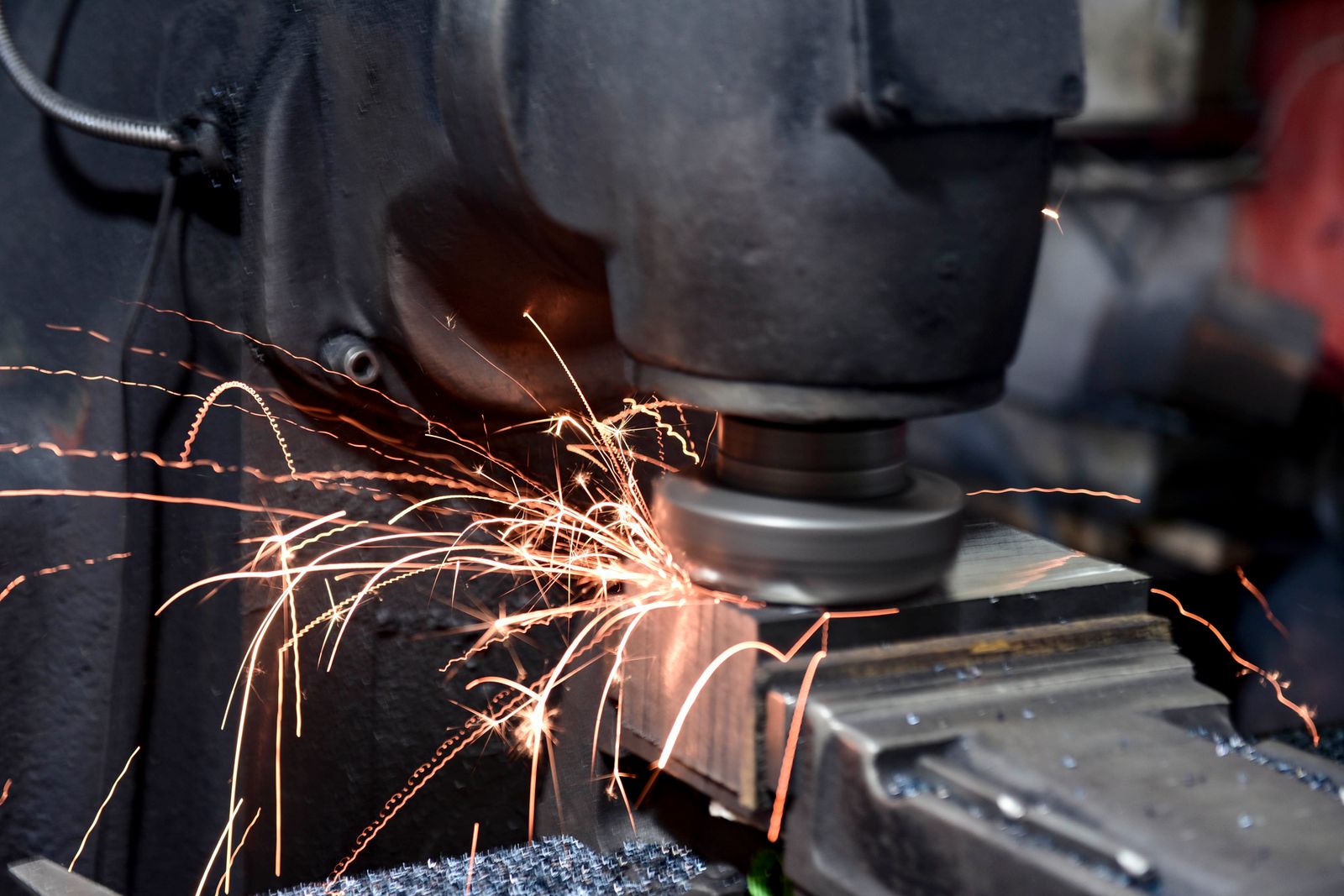
Ground parts are packed to protect the finished face from impact, corrosion, and contact damage. Precision ground faces are typically wrapped in VCI paper, separated by foam, and shipped in rigid cartons or crates to prevent movement during transit.
- Standard packaging — VCI wrap, foam separators between ground faces, individual cardboard sleeves, layer-pad cartons, and labelled kits per part number.
- Precision shim packaging — small shims are stack-packed between cardboard or foam and tape-banded to prevent splay; thickness and quantity are clearly labelled.
- Large-part packaging — V-block supports, custom wooden crates, and edge protectors for plates above 300 — 600 mm.
- Shipping options — air freight, sea freight (FCL / LCL), road, and courier; EXW, FOB, CIF, and DAP incoterms supported.
- Standard documents — packing list, commercial invoice, certificate of conformance (C of C), material test certificate to EN 10204 3.1.
- Inspection documents — first-article report (AS9102 / PPAP), flatness and parallelism report on a calibrated granite plate, surface-roughness trace, hardness and dimensional records.
- Traceability — heat- and lot-number linkage from raw stock through grinding, heat-treat, and shipment; serialisation on request.
Related Capabilities & Cross-Services
Surface grinding is normally one step in a larger part process. The following capabilities are commonly combined with surface grinding to deliver a finished, inspected, and protected component.
- CNC milling (3-axis, 4-axis, 5-axis) — pre-machining of the blank to near-final geometry before the surface-grind step.
- CNC turning and lathe work — cylindrical features, register diameters, and seal faces that share the part's primary datum.
- Cylindrical and centreless grinding — OD and shoulder features that work with the ground face.
- Wire EDM and sinker EDM — sharp internal corners, slots, and small features on hardened material.
- Lapping and super-finishing — sub-?m flatness and mirror finish on sealing faces, gauge blocks, and reference plates.
- Heat treatment — through-hardening, case-hardening, induction hardening, nitriding, and stress relief through approved partners.
- Surface finishing — passivation, black oxide, electroless nickel, hard chrome, and PTFE / dry-film coating on the ground face when required.
- Deburring and edge finishing — chamfering, edge-breaking, and hand-finishing to clean up ground edges.
- Laser marking and engraving — part numbers, datum letters, and traceability codes on the un-ground side of the part.
- Cleanliness and protection — washing, rust-preventative oil, VCI wrap, and individual packaging for long-distance shipments.
Feature families
Functional features include flat sealing faces, parallel ways, bearing or slide surfaces, precision spacers, ground tool faces, wear plates, and reference surfaces that control an assembly.
Functional outcome | What the drawing should identify |
|---|---|
Fit / movement / sealing | Identify the primary datum, the flatness or parallelism requirement, thickness dimension, finish expectation, stock condition, and any zones that must remain unground. Heat-treated or thin parts need an explicit distortion-control review. |
Part context | Typical parts include machine components, fixture plates, die inserts, precision shims, slide elements, hardened wear parts, tooling blocks, and ground mounting interfaces. |
Inspection-ready RFQ
Supply | Why it matters |
|---|---|
Datum scheme and critical geometry | Connects the final surface to the part's functional reference. |
Mating-part or fit information | Lets the process plan focus on the interface that actually controls performance. |
Surface and edge expectation | Avoids treating cosmetic and functional requirements as the same thing. |
Standard Tolerances & Achievable Precision
Surface grinding is the right process when flatness, parallelism, or finish is the controlling feature. Tight tolerance is held by combining a stable magnetic or mechanical hold, a sharp dressed wheel, light spark-out passes, and verified thermal stability.
- Flatness: 0.005–0.020 mm over 300 mm; 0.01 mm / m on precision passes
- Parallelism: 0.01–0.03 mm between opposite faces
- Thickness: ±0.01 mm on shim work; ±0.025 mm standard
- Surface finish: Ra 0.2–1.6 µm depending on wheel specification and number of spark-out passes
- Squareness to a reference face: 0.01–0.03 mm / 100 mm
- Default linear tolerance per ISO 2768-m where the drawing does not specify otherwise
Surface Finish Options
- As-ground finish — typical Ra 0.2–1.6 µm depending on wheel specification
- Fine finish with a dressed, finer-grit wheel for sealing faces, bearing surfaces, and reference datums
- Cross-hatched lay pattern (controlled by table speed and traverse) where the function benefits
- Deburring and edge-breaking at all external edges to prevent handling damage
- Light honing or lapping for ultra-flat reference faces on request
- Post-grind finishes: black oxide, passivation, light oil, rust-preventative film, or protective wax
- Plating and painting on opposite (un-ground) faces when the drawing requires it
- Laser marking and engraving for part numbers, datums, and traceability codes
Design Considerations (DFM Tips)
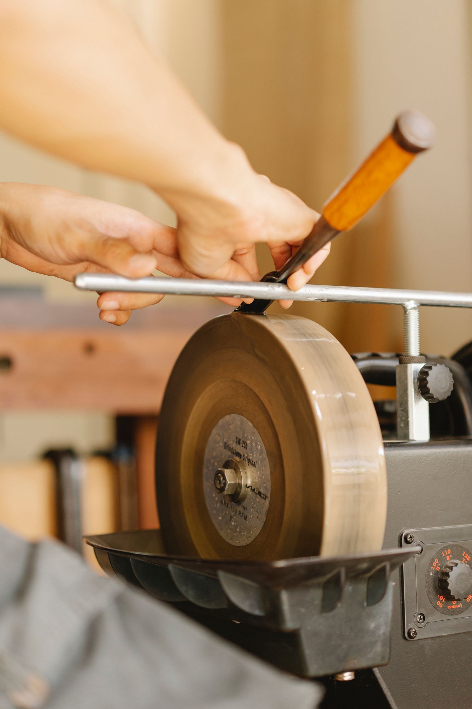
- Define a single primary ground datum and reference other features to it. A clear datum reduces fixturing and inspection time.
- Indicate flatness and parallelism separately. A part may need both — but a single tight call-out reduces ambiguity at inspection.
- For thin parts, state the maximum thickness and confirm the part can be held flat during grinding. Unsupported thin sections deflect under the magnetic chuck.
- For hardened parts, indicate the hardness spec and any prior heat-treatment steps. Heavy stock on hardened steel drives up wheel wear and cycle time.
- Identify protected zones that must not be ground — for example, a pre-machined locating face or a hardened area. The fixture and program plan around them.
- Allow a small chamfer or edge break on all external edges of the ground face to avoid chipping and handling damage.
- If both sides of the part must be parallel, indicate whether to grind both sides or grind one and skim the other. Two-sided grinding adds setup time.
- For through-hardened or interrupted surfaces, flag the area on the print so a steadier wheel and softer parameters can be used.
- Specify the final finish expectation with a Ra value, not a qualitative description like "smooth" or "fine".
Industries & Applications
- Mould and die — die set reference faces, bolster plates, ejector retainer plates, guide pin bushings
- Industrial machinery — fixture plates, machine tool ways, ground spacers, precision shims
- Automotive — brake shim plates, transmission separator plates, valve body reference faces
- Aerospace — sealing faces on actuators, ground reference plates for assembly jigs
- Hydraulics and fluid power — valve sealing faces, manifold mating surfaces, pump cover faces
- Tooling and gauges — precision squares, angle plates, gauge blocks, sine plates
- Semiconductor and electronics — vacuum chamber reference plates, fixture bases for inspection systems
Can you grind hardened parts?
Yes. Surface grinding is well suited to hardened steels, tool steels, and carbide up to HRC 65, with the right wheel specification, dressing strategy, and coolant. The hardness spec should be on the drawing so the right wheel is selected.
- Sealing surfaces
- Reference datums
- Precision shims
- Hardened wear plates
- Ground tool faces
—
How thin can a part be and still be ground flat?
Thin parts (under about 2 mm) need extra care: a fine-pitch magnetic chuck, a carrier plate, or a dedicated fixture. We review thin-section work at the quote stage so the right fixturing is planned in.

