

Frequently Asked Questions
What is the typical stock allowance for cylindrical grinding?
For pre-machined or pre-heat-treated parts, 0.2–0.4 mm per side is typical. Hardened tool or bearing steel may need 0.3–0.5 mm per side so the wheel can correct distortion and decarburization.
Can cylindrical grinding reach ±0.0025 mm on diameter?
Yes, on selected features with a precision cylindrical grinder, proper wheel dressing, and a stable part. It is typically reserved for bearing seats, gauge features, and reference diameters, not the entire part.
What's the difference between cylindrical and centerless grinding?
Cylindrical grinding holds the part on centers or in a chuck, so it's suited to parts with a defined axis, shoulders, tapers, and internal diameters. Centerless grinding feeds the part between a regulating and grinding wheel and is best for high-volume small cylindrical features without shoulders.
Controlled feature | Roundness, runout, and surface finish on rotational surfaces |
|---|---|
Typical workpieces | Shafts, spindles, rollers, sleeves, and precision bores |
Holding method | Centers, chuck, or fixture aligned to the functional axis |
Source review | Functional axis plus inspection plan for roundness and runout |
Wheel Contact and Heat
Hardened steel, alloy steel, stainless steel, tool steel, cast iron, and selected nonferrous materials may be considered. Material hardness, wheel selection, rigidity, and coolant control influence the feasible outcome.
Finish and protection
Protect precision diameters during handling and subsequent finishing. If coatings are required, define whether they occur before grinding or require a controlled post-coating grind.
Question | Reason to resolve it before release |
|---|---|
Is the part heat treated? | Material condition can change wheel choice, stock allowance, and distortion risk. |
What edge condition is acceptable? | Functional edges, cosmetic faces, and assembly interfaces can require different deburring instructions. |
Checking Roundness and Runout
Inspection priorities typically include diameter, roundness, cylindricity, taper, runout, shoulder location, surface finish, and the fit with the mating bearing, seal, or bore.
Key Process Parameters
Parameter | Typical Value |
|---|---|
Diameter tolerance | ±0.005 mm to ±0.025 mm standard, ±0.0025 mm on request |
Roundness | 0.001 mm to 0.003 mm (depending on diameter and material) |
Cylindricity | 0.003 mm to 0.008 mm over full feature length |
Runout to datum axis | 0.002 mm to 0.005 mm TIR |
Surface finish Ra | 0.2 —m to 0.8 —m (8 to 32 —in) |
Max part diameter (OD) | Up to 320 mm (larger on request) |
Max part diameter (ID) | Up to 200 mm bore |
Max grinding length | Up to 1000 mm between centers |
Min feature length | 1 mm shoulder or face |
Batch range | 1 prototype to 5000+ production pieces |
Standard lead time | 5–10 working days for prototypes, 2–4 weeks for production |
Accepted file formats | STEP, IGES, X_T, DWG/DXF, PDF drawing |
Typical machine | Studer S33, Studer S31, Okamoto ACC, Shigiya GPS, cylindrical OD/ID grinders with C-axis dressers |
Materials We Machine
- Hardened alloy steels – 4140, 4340, 8620 (through-hardened to 28–62 HRC).
- Bearing and tool steels – 52100 (SUJ2), A2, D2, H13, S7, M2, SKD11, SKD61.
- Stainless steels – 304, 316, 410, 420, 17-4 PH, 15-5 PH (annealed or H900–H1150).
- Carbon and structural steels – 1018, 1045, A36, S355.
- Case-hardened steels – pre- and post-grind finishing of carburized or nitrided surfaces.
- Cast irons – gray cast iron, ductile (nodular) iron, CGI.
- Nonferrous alloys – aluminum 6061/7075, brass C360, copper C110, bronze C932.
- Tool and high-speed steels – AISI M2, M4, T1, ASP2060.
- Super alloys – Inconel 625/718, Hastelloy, Monel 400 (with CBN wheels).
- Hard chrome and nitrided surfaces – finish grinding after plating or nitriding.
Standard Tolerances & Achievable Precision
Cylindrical grinding is a finishing process, so tolerances are typically tighter than turning or milling. The numbers below are realistic values on production cylindrical grinders and depend on part rigidity, wheel selection, and material condition.
- ±0.025 mm general cylindrical grinding tolerance (default).
- ±0.010 mm precision cylindrical grinding on hardened bearing and tool steels.
- ±0.0025 mm ultra-precision on selected features with CMM-verified process.
- ISO 2768-m as default general tolerance, ISO 2768-f for tighter callouts.
- Roundness 0.001 mm achievable on small-diameter hardened shafts.
- Cylindricity 0.003 mm per 100 mm typical length.
- Runout 0.002 mm to 0.005 mm TIR to functional datum.
Quality Control & Inspection
All cylindrical-ground features are measured against the drawing's functional datum. Typical inspection scope includes:

- CMM (Zeiss, Hexagon, Mitutoyo) – full GD&T verification including roundness, cylindricity, concentricity, runout, and profile.
- Roundness / form tester – Taylor Hobson Talyrond or equivalent for roundness, cylindricity, and harmonic analysis.
- Surface roughness tester – Mitutoyo SJ-210 or Mahr Pocket Surf for Ra, Rz, and profile traces.
- Hardness tester – Rockwell, Vickers, or Brinell for through-hardened and case-hardened surfaces.
- Calipers and micrometers – 0.001 mm resolution OD/ID micrometers, depth micrometers, and bore gauges for in-process checks.
- First-article inspection (FAIR / AS9102) – full dimensional report on the first-off part before production run.
- In-process checks – diameter, roundness, and surface finish measured at defined intervals during the run.
- Final inspection report – digital report with measured values, CMM PDF, and material / heat-treat certificates when required.
Design Considerations (DFM Tips)
- Allow a clean center hole or center-indent area – between-centers work needs consistent datums to control runout.
- Provide stock for grinding on hardened features – 0.2 mm to 0.4 mm per side is a safe allowance for finish-grind of pre-hardened stock.
- Avoid deep narrow grooves – groove width should be ±3— the wheel radius to allow dressing and reach.
- Use radii instead of sharp corners – 0.5 mm min corner relief reduces wheel burn and chatter.
- Specify runout to a functional datum, not a stock surface – tie circularity and concentricity to the same axis the part rotates on in assembly.
- Call out surface finish per feature – bearing seat Ra 0.4 —m is different from a non-functional journal at Ra 1.6 —m.
- Avoid thin walls in grinding fixturing – distortion under wheel pressure can be controlled by material, fixturing, or grinding strategy.
- Consider heat-treat sequence – grind after heat treat whenever final hardness and geometry must both be achieved.
- Add a safe clamping zone – protect finished diameters by leaving an unmachined shoulder for chuck or fixture contact.
- Distinguish sealing vs bearing diameters – a seal surface typically needs a tighter finish and roundness than a non-critical journal.
How to Get a Quote
Send us your 3D CAD file (STEP, IGES, X_T, or native), 2D drawing with GD&T, material grade and condition (annealed vs. pre-hardened), required quantity, target surface finish, critical tolerances, and any mating-part or assembly information. We return a DFM review focused on datums and stock allowance, a realistic lead time, and a unit price broken down by raw material, machining, grinding, inspection, and finishing.
Process Flow & Manufacturing Sequence
Cylindrical grinding is typically the last machining step before inspection and ship-out. The sequence below is the standard route from incoming stock to a certified, ground feature. Sub-steps are adjusted for material condition (annealed vs pre-hardened), stock allowance, and the feature priority called out on the drawing.
- Material receipt and verification – Incoming bars or pre-machined blanks are checked against the MTC (mill test certificate) for grade, heat number, and condition. Hardness is verified on a sample coupon or directly on the stock when the MTC is missing.
- Pre-machining (turning / milling) – OD roughing and finishing on a CNC lathe leave a defined stock allowance of 0.2–0.4 mm per side for finish grinding, and 0.3–0.5 mm per side for hardened or distorted stock. Center holes (DIN 332 Form R or AR) are drilled or reamed to support between-centers work.
- Stress relief (when applicable) – Pre-hardened or heavily machined components receive a sub-critical stress relief (e.g. 580–620 —– for alloy steel) before hardening to reduce distortion in heat treat.
- Heat treatment – Through-hardening, carburizing, nitriding, or induction hardening is performed by a qualified sub-supplier. Hardness, case depth, and metallurgical requirements are validated on coupons or witness samples.
- Post-HT straightening (when needed) – Long slender shafts are checked for runout; parts beyond 0.05–0.1 mm TIR are pressed or rotary straightened to keep stock on the wheel consistent.
- Clean and pre-grind prep – Oxide scale and decarburization are removed by light cylindrical skimming or belt sanding where required; center holes are re-cut or lapped to restore clean datums.
- Setup on the cylindrical grinder – Part is mounted between centers, in a 3-jaw chuck, or on a mandrel/fixture depending on the feature. Wheel is dressed to the required profile using a single-point diamond or rotary dresser.
- Rough grind – High specific material removal rate (Q' > 8 mm?/mm—s) with a 60-grit aluminum-oxide or CBN wheel. Multiple spring passes ensure thermal stability.
- Spark-out and fine grind – Lower wheel speed and feed (Q' 0.5–2 mm?/mm—s) with a 80–120 grit wheel, finishing to the target diameter, roundness, cylindricity, and Ra.
- Shoulder / face / taper grinding – Angular wheel dressing or a separate operation produces the shoulder relief, face land, or taper specified on the print.
- ID grinding (when applicable) – Internal diameters are ground on a dedicated ID grinder or on a universal cylindrical grinder with an internal attachment.
- Superfinishing (when specified) – A fine-grit stone oscillates under low pressure on the part to refine Ra below 0.1 —m for bearing or sealing surfaces.
- Deburr and wash – Light hand-deburr or rotary brush removes feather edges, followed by aqueous wash and dry.
- Final inspection – Dimensional, geometric, and surface-finish checks against the print. CMM, Talyrond, and Perthometer traces are archived.
- Marking, packaging, and release – Laser marking of part number / lot, anti-corrosion VCI bag, foam-padded carton, and C of C issue.
Material Property Reference
Reference values for materials commonly finished by cylindrical grinding. Tensile/yield strength and hardness are typical for the condition most often ground; machinability is referenced against AISI 1212 steel at 100%.
Material | Density (g/cm?) | Tensile Strength (MPa) | Yield Strength (MPa) | Hardness (HB) | Machinability Rating (%) |
|---|---|---|---|---|---|
Low-carbon steel 1018 (as-rolled) | 7.87 | 440 | 370 | 131 | 70 |
Medium-carbon steel 1045 (annealed) | 7.85 | 625 | 530 | 190 | 55 |
Alloy steel 4140 (Q&T 28–32 HRC) | 7.85 | 1020 | 900 | 290 | 50 |
Bearing steel 52100 (through-hardened) | 7.81 | 2240 | 1900 | 650 (HV) | 35 (CBN recommended) |
Tool steel D2 (Q&T 58–60 HRC) | 7.70 | 1860 | 1650 | 620 (HV) | 25 (CBN only) |
Tool steel H13 (Q&T 50–52 HRC) | 7.80 | 1640 | 1380 | 530 | 40 |
Stainless 304 (annealed) | 8.00 | 620 | 290 | 180 | 45 |
Stainless 17-4 PH (H900) | 7.78 | 1380 | 1280 | 420 | 40 |
Nitrided 4140 (case 0.5 mm) | 7.85 | 1100 | 950 | 950 HV1 (case) | 30 (CBN / ceramic) |
Inconel 718 (aged) | 8.19 | 1430 | 1180 | 460 | 12 (CBN / ceramic) |
Aluminum 6061-T6 | 2.70 | 310 | 276 | 95 | 180 |
Brass C360 (as-drawn) | 8.50 | 510 | 380 | 130 | 100 |
Gray cast iron Class 30 | 7.20 | 260 | — | 210 | 75 |
Cost Drivers & Lead Time Factors
Cost and lead time in cylindrical grinding are dominated by material condition, stock removal, and how many features must be controlled tightly. Hardened parts require finer, slower cuts with CBN or ceramic wheels; long slender shafts need between-center support; tight GD&T adds inspection time. The numbers below are typical for small-to-medium lot production in a job-shop environment.
Scenario | Quantity | Typical Lead Time | Primary Cost Drivers |
|---|---|---|---|
Soft steel prototype, 1–5 pieces | 1–5 off | 3–7 working days | Setup time, single-point fixturing, CMM inspection |
Hardened 4140 short run, ±0.01 mm | 10–50 off | 7–12 working days | Heat-treat queue, CBN wheel prep, dressing program |
Bearing steel 52100, ±0.005 mm | 50–200 off | 2–3 weeks | Heat-treat cert, CMM, FAIR/AS9102, segregation |
Production shaft, ±0.01 mm, 1000+ off | 1000–5000 off | 3–5 weeks | Cycle time, wheel life, in-process gauging, packaging |
Inconel 718 shaft, ±0.01 mm | 20–100 off | 3–5 weeks | CBN wheel cost, low MRR, swarf containment, cert |
ID grinding, hardened sleeve, ±0.005 mm | 10–50 off | 2–3 weeks | Internal quill setup, mandrel, bore gauge inspection |
Long shaft >600 mm, 4 journals | 5–25 off | 2–4 weeks | Long-bed grinder, steady rests, runout control |
Aerospace, full FAIR / AS9102 | any | +3–7 days vs standard | First-article inspection, traceability, FAI report |
Common Defects & Prevention
Defect | Cause | Prevention |
|---|---|---|
Thermal burn (white or dark re-tempered layer) | Excessive wheel contact, dull wheel, low coolant flow, or material with low thermal conductivity | Use sharp wheel, reduce infeed, increase spark-out passes, verify coolant nozzle alignment, switch to CBN on hardened parts |
Chatter / waviness on the ground surface | Regenerative vibration from wheel/part/regulator system, loose centers, worn spindle bearings | Balance the wheel, dress concentric, check spindle runout, increase work speed, add damping, verify center quality |
Taper along the part length | Misaligned work-spindle axis to wheel, headstock/footstock misalignment, uneven wear across wheel face | Re-align the machine to a test bar, true the dresser to the table, dress the wheel to compensate |
Poor roundness (lobed or oval form) | Centers worn, work distorted by clamping force, spindle runout, harmonics from the regulator | Lap or replace centers, switch to a 4-jaw chuck with runout check, verify spindle TIR, relieve internal stress before finish |
Wheel loading (glazed surface, burn streaks) | Soft workpiece material smearing into wheel pores, wrong grade for material, insufficient dressing | Use more open-structure wheel, switch to a softer grade, dress more frequently, consider a different bond |
Surface roughness spikes or tearing | Contaminated coolant, dirty part, damaged wheel grit, feed too high in last pass | Filter and change coolant, clean workholding, redress wheel, add a spark-out pass with reduced feed |
Dimensional drift over a production run | Wheel wear, thermal growth of spindle/part, coolant temperature rise, dresser compensation drift | Periodic in-process gauging, dress compensation, stabilized thermal environment, automatic wheel-dress cycles |
Workpiece deflection under wheel pressure | Long slender part, weak fixturing, excessive radial force during roughing | Add a steady rest, reduce roughing infeed, take equalized passes from both ends, switch to a higher-modulus material |
Comparison With Related Processes
Aspect | Cylindrical Grinding | Alternative | When to Choose |
|---|---|---|---|
Hard-material capability | Up to 65 HRC with CBN or ceramic wheels | Hard turning: up to 62 HRC with PCBN tooling | Choose grinding for hardened diameters below ±0.01 mm, tight roundness, and finish below 0.4 —m Ra |
Throughput | Slower per part, but consistent and stable on long runs | Hard turning: higher MRR, faster cycle time | Choose grinding when part count is medium, or when finish/IT grade must be combined with form control |
Part geometry | Stepped shafts, shoulders, tapers, internal diameters, keyways on finish | Centerless grinding: straight simple cylinders only | Choose cylindrical for parts with features, concentric features, or internal diameters |
Surface integrity | Compressive residual stress, low metallurgical damage when parameters are controlled | Hard turning: possible tensile residual stress and white layer | Choose grinding for fatigue-loaded shafts, bearings, and rotating components |
Workholding | Between centers, chuck, or mandrel — defined datums | Centerless: work-rest blade, no defined datum | Choose cylindrical when concentricity / runout to a specific datum is critical |
Packaging, Shipping & Documentation
Ground features are protected from in-transit damage and from in-house corrosion. The packaging scheme scales with part size, surface sensitivity, and destination. Standard documents accompany every shipment, with aerospace and medical paperwork issued on request.
- Primary wrap – Anti-corrosion VCI (volatile corrosion inhibitor) paper or bag for ferrous parts; clean-room-grade poly bag for medical and semiconductor ground parts.
- Part separation – Foam pouches, individually machined cavities, or corrugated dividers prevent diameters from contacting each other.
- Outer carton – Double-wall corrugated with edge protectors; custom plywood crate for shafts longer than 600 mm or any assembly over 25 kg.
- Shock & tilt indicators – Included on aerospace, medical, and high-value shipments for tamper-evidence.
- Labeling – Each bag or partition labeled with part number, lot, and quantity; outer carton marked with gross weight, dimensions, and HS code.
- Shipping options – Standard freight, expedited air, and DDP/DAP international forwarding. Hand-carry for critical spares on request.
- Standard documents – Certificate of Conformance (C of C) with drawing and revision reference.
- Material certificate – Mill Test Certificate (MTC) or 3.1 / 3.2 inspection certificate per EN 10204.
- Heat-treat certificate – Furnace run, hardness, and case-depth report when heat treat is in scope.
- First-article report – AS9102 FAIR or equivalent CMM dimensional report for the first production part.
- In-process / final inspection report – Digital PDF with measured dimensions, roundness / cylindricity traces, and surface-finish values.
- Traceability – Heat number, lot, and operator stamps retained in the digital traveler for at least 7 years (aerospace / medical: 30 years).
The Rotational Datum
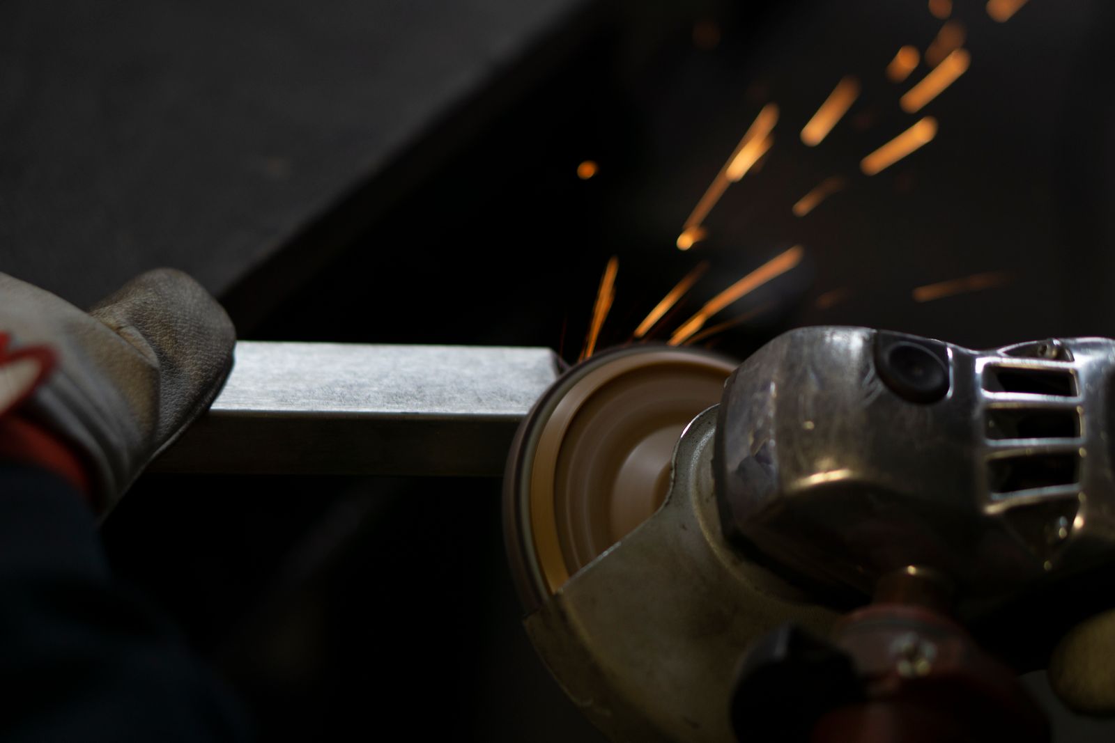
Cylindrical grinding refines round outside or inside diameters by presenting an abrasive wheel to a rotating workpiece. It is often selected for shafts, journals, bores, tapers, and other rotational features where size, roundness, runout, or surface condition is more critical than rough machining alone can reliably provide.
Feature families
Suitable features include bearing journals, sealing diameters, tapered seats, close-fit shafts, precision bores, valve spools, roller surfaces, and concentric stepped diameters.
Functional outcome | What the drawing should identify |
|---|---|
Fit / movement / sealing | Define the functional axis and call out diameter, length, runout, concentricity, taper, surface finish, and mating component where relevant. Provide centers, chucking allowance, or a safe clamping zone if the part design needs it. |
Part context | Typical components include shafts, spindles, rollers, hydraulic parts, precision sleeves, drive-system components, gauge parts, and post-heat-treatment tooling. |
Diameter, Taper, and Shoulder Strategy
The route starts by locating the component on centers, a chuck, or a fixture relative to its functional axis. The wheel is dressed, the work is roughed toward size, and finish passes are planned to achieve the required diameter, surface condition, and relationship to shoulders or adjacent features.
Before grinding | During grinding | After grinding |
|---|---|---|
Stock allowance, datums, stable support | Wheel condition, heat, passes, coolant, geometry checks | Deburr, protect, inspect, package |
PROCESS RISK: Heat, thin sections, interrupted surfaces, and unstable support can matter as much as nominal dimension.
Inspection-ready RFQ
Supply | Why it matters |
|---|---|
Datum scheme and critical geometry | Connects the final surface to the part's functional reference. |
Mating-part or fit information | Lets the process plan focus on the interface that actually controls performance. |
Surface and edge expectation | Avoids treating cosmetic and functional requirements as the same thing. |
Surface Finish Options
- As-ground – 0.4 —m Ra typical on steel, 0.2 —m Ra on hardened bearing steels.
- Fine grinding / superfinishing – down to 0.05 —m Ra for sealing or bearing surfaces.
- Bead blast (glass bead / aluminum oxide) – uniform matte appearance without dimensional change.
- Passivation – ASTM A967 / A380 on stainless steels after grinding.
- Black oxide – MIL-DTL-13924D Class 1 or 4 over ground surface.
- Electroplating – hard chrome, electroless nickel, or decorative chrome applied before or after finishing grind.
- Hard anodize (Type II / Type III) – for aluminum shafts and sleeves.
- Powder coat and wet paint – with masking of precision diameters and bearing seats.
- Polishing – mirror finish on stainless or aluminum decorative features.
- Laser marking – part numbers, datums, or traceability on shoulders or faces away from the ground diameter.
Should I grind before or after heat treat?
For tight tolerances and hardened surfaces, grind after heat treat. Hard turning followed by finish grinding is also common for high-volume parts where cycle time matters.
What surface roughness can you achieve?
Standard cylindrical grinding reaches 0.2–0.4 —m Ra on steel. With superfinishing or fine-grinding passes, 0.05–0.1 —m Ra is achievable on bearing and sealing surfaces.
Do you provide inspection reports?
Yes. A standard inspection report with measured dimensions and surface finish is included, and full CMM / FAIR (AS9102) reports are available on request.
Industry Standards & Certifications
- ISO 9001:2015 – Quality management system baseline; standard for general industrial customers.
- AS9100D – Aerospace QMS required for flight-critical shafts, landing-gear pins, and actuator rods.
- ISO 13485:2016 – Medical device QMS for surgical-instrument shafts, orthopedic handles, and dental blanks.
- IATF 16949 – Automotive QMS for transmission, steering, and driveline components.
- NADCAP AC7110 / AC7112 – Special-process accreditation for heat treat and surface enhancement used on hardened parts prior to grinding.
- RoHS & REACH – Compliance for European markets; restricts certain substances in any coating or finishing applied after grinding.
- ITAR – Required for defense articles and controlled parts; restricts data flow and traceability.
- ISO 2768-1 / ISO 2768-2 – General tolerance (medium / fine) for un-toleranced dimensions on drawings.
- ASME Y14.5-2018 – GD&T symbol and rule set applied to datums, runout, and profile callouts.
- ISO 5459 – Datums and datum systems referenced in inspection reports.
- ASME B89.1.5 / ISO 230 – Acceptance and reproducibility tests for machine tools used in qualification.
- ISO 10360 – Acceptance test for CMM used to verify ground features.
- SAE AS9102 – First-article inspection report format for aerospace.
Related Capabilities & Cross-Services
Cylindrical grinding is rarely the only process in a precision shaft or sleeve. The following capabilities pair with cylindrical grinding on the same part, the same lot, or the same supply agreement. Combining them on a single PO reduces handling, transit, and inspection time.
- CNC turning (OD roughing / pre-grind) – Pre-grind stock preparation on lathes with live tooling, leaving defined stock allowance for finish-grind features.
- Hard turning (pre-grind for hardened parts) – PCBN tooling removes 80–95% of the stock before grinding, reducing cycle time on heat-treated shafts.
- Surface grinding – Companion process for shoulders, faces, and flat reference datums on the same shaft or housing.
- Centerless grinding – Used when the same lot includes high-volume, simple-diameter pins or rods that do not need between-centers work.
- ID grinding – Internal diameters and bores on the same part as OD-ground features.
- Superfinishing / honing – Final surface refinement for sealing and bearing surfaces below 0.1 —m Ra.
- Lapping – Hand or machine lapping of gauge pins, master rings, and reference diameters after cylindrical grinding.
- Heat treatment – Through-hardening, induction hardening, nitriding, and case-hardening coordinated with the grinding sequence.
- Wire & Sinker EDM – Pre-grind shaping of slots, keyways, and complex features that would be hard to grind in-place.
- Hard chrome / electroless nickel plating – Applied before or after finish grinding depending on tolerance stack-up.
- Passivation, black oxide, and anodizing – Surface conversion on stainless, carbon, and aluminum ground parts.
- CMM, Talyrond, and Perthometer inspection – Verified metrology data attached to the C of C.
- Reverse engineering and sample matching – Re-creating a ground feature from a worn or sample part.
- Bearing journals
- Sealing diameters
- Tapered seats
- Spindles and drive components
- Gauge parts
Industries & Applications
- Automotive – transmission shafts, pinion shafts, valve spools, pump rotors, steering components.
- Aerospace – actuator rods, landing-gear pins, hydraulic spools, flap-track components.
- Medical – surgical instrument shafts, orthopedic instrument handles, dental drill blanks.
- Hydraulics & fluid power – piston rods, cylinder barrels, valve spools, pump shafts.
- Power transmission – bearing journals, gear shafts, motor shafts, gear-box spacers.
- Industrial machinery – rollers, idler shafts, guide posts, machine-tool spindles.
- Energy – turbine shafts, generator components, oil & gas downhole parts.
- Semiconductor / metrology – precision gauge pins, locating sleeves, calibration hardware.
—
—

