

Large component planning
The document is organized around these four planning lenses.
Selection guidance
Choose a large-part milling route when the part is predominantly prismatic and requires broad tool access. Large turning is more appropriate for rotational components; large boring can be the controlling process where critical internal diameters dominate.
Frequently Asked Questions
What is the largest part you can mill?
Our bridge-type machining centers reach approximately 2000 — 1500 — 800 mm. Long-bed mills extend the X-axis to 4000 mm or more. For parts outside the standard envelope, we review fixturing, handling, and datum strategy before confirming capacity.
Geometry | Large prismatic faces, pockets, and mounting patterns |
|---|---|
Planning focus | Work envelope, lifting, clamping, and datum path |
Material | Aluminum plate, steel, stainless, cast iron, weldments |
Typical use | Machine frames, base plates, large fixtures, structural housings |
Work Envelope, Mass, and Clamping
Large part milling applies CNC milling to components whose size, weight, travel requirements, or handling needs become material planning constraints. The central question is not only whether a part fits a machine table, but whether it can be safely clamped, reached by appropriate tools, machined from all required directions, and inspected against its functional datums.
Large-part milling plans the work envelope, lifting, clamping, and datum path before the cutting sequence.
Planning lens | What to provide |
|---|---|
Part envelope | Finished size, stock condition, estimated mass, and any no-clamp zones. |
Handling | Lift points, support requirements, transport limitations, and surface-protection constraints. |
Functional geometry | Provide an overall envelope, estimated finished weight, stock method, lifting or clamping zones, critical datums, machine-interface requirements, and whether the part is a weldment, casting, plate, or forged item. |
Stability of Large Milled Structures
Material considerations commonly include aluminum plate, steel, stainless steel, cast iron, and welded structures. Material stability, residual stress, weight, chip management, and corrosion requirements should all be reviewed.
Protection plan
Large parts should be protected from handling marks and corrosion during the manufacturing route. Coating or painting plans should account for critical machined faces and threaded holes.
Potential issue | Planning response |
|---|---|
Residual stress or distortion | Sequence roughing and finishing with the material condition and support plan in mind. |
Handling damage | Define protective surfaces, lifting method, and packaging before the final machining step. |
Coating on critical interfaces | Specify masking or a controlled post-finish operation. |
Materials We Machine
Large-part milling routinely handles aluminum plate, mild and alloy steel, stainless steel, cast iron, and weldments produced to near-net shape before finish machining. Material selection is matched to the structural and surface requirements of the part.
- Aluminum alloys: 6061-T6, 6082-T6, 7075-T6, 2024, 5052 plate and billet
- Mild steel: A36, A572, S275JR, S355JR plate; 1018, 1026, A36 bar
- Alloy steel: 4140, 4340, 8620 normalized or pre-hardened; EN24, EN19
- Stainless steel: 304 / 304L, 316 / 316L, 321, 310S, 17-4PH (H1025 / H1150)
- Cast iron: ASTM A48 Class 30 / 40, GG25, GGG40 / GGG60 ductile iron
- Tool & wear steel: A2, D2, H13, O1 pre-machined plate or forged blanks
- Weldment & fabrication stock: welded steel assemblies stress-relieved before finish machining
- Engineering plastics (limited): UHMW-PE, Delrin / POM, nylon, phenolic plate for support or wear surfaces
Quality Control & Inspection
Inspection plans for large milled parts focus on functional datums, large-scale geometry, and the relationship between features that depend on multiple setups. Routine measurements are taken with calibrated hand tools; critical features are released on CMM or laser-based equipment.
- CMM inspection: bridge-type and horizontal-arm CMMs for large parts, with probing against the defined datum scheme
- Surface roughness tester: portable Ra testers for as-machined and post-finish surfaces
- Hardness tester: portable or bench hardness testing (Rockwell, Brinell, Vickers) for material certification
- Calipers & micrometers: calibrated digital and analog hand tools for in-process checks
- Height gauges & surface plates: Grade-A surface plates with digital height and depth gauges
- First-article inspection: full-dimensional report against drawing or model before production run continues
- In-process inspection: datum and feature checks between setups to control drift across multiple orientations
- Final inspection report: dimensional report, material certificate, and finish confirmation shipped with the part
What is the typical lead time for a first large milled part?
First-of-kind parts typically run 10 – 15 working days including DFM review, fixturing, and inspection. Recurring production parts usually run 5 – 10 working days depending on batch size and material availability.
How to Get a Quote
To quote a large-part milling job, send the 3D model (STEP, IGES, Parasolid, or native CAD), 2D drawing with GD&T and datums, material grade and condition, batch quantity, any required finish, critical tolerances, and inspection expectations. For weldments, include the weld procedure, stress-relief record, and any required post-machining.
You will receive a DFM review with comments on envelope, clamping, datum strategy, and any tolerance refinements, followed by a written quote that lists lead time, unit price, finish options, and inspection report scope.
Process Flow & Manufacturing Sequence
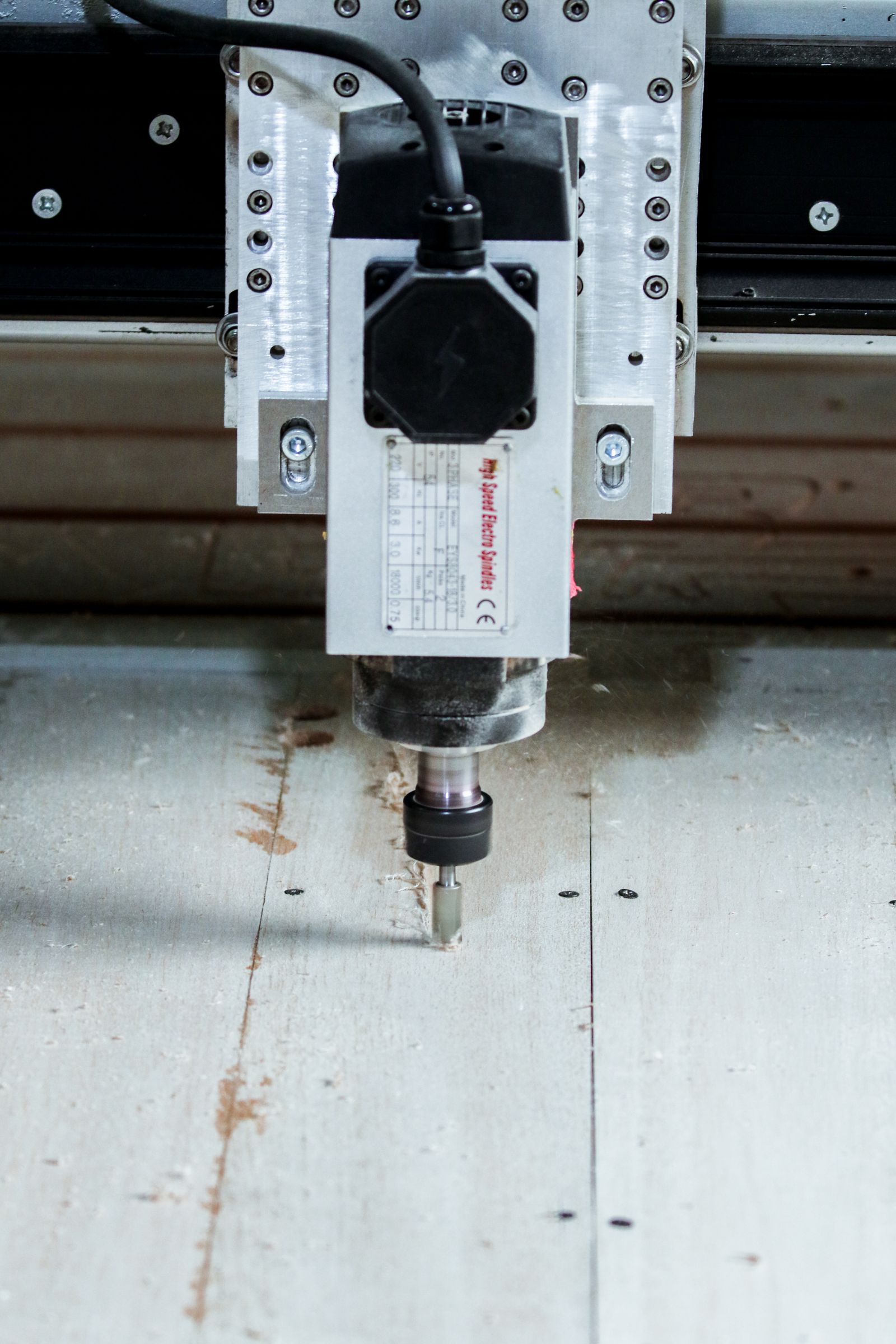
Large-part milling follows a defined sequence from incoming stock verification to final inspection. The route is built around the part envelope, material condition, datum scheme, and the order in which features must remain co-located. Each step below is a discrete production operation with its own setup, tooling, and inspection checkpoint.
- Material receipt & verification. Incoming stock is checked against the purchase order and material certificate: grade, heat number, condition (hot-rolled, normalized, pre-hardened), and dimensional stock size. Stock allowance is confirmed against the part drawing.
- Stock cutting & pre-machining prep. For raw plate or bar stock, saw cutting or abrasive cut-off brings the blank closer to the rough envelope. For weldments, the rough weldment is stress-relieved (where required) and shot-blasted before machining prep.
- Datum identification & indicator setup. The machinist identifies the primary, secondary, and tertiary datums on the model and on the blank, then indicates the stock to confirm fixture plan, lift points, and clearance for the tool.
- Workholding & fixture build. Heavy-duty fixtures, toe-clamps, step blocks, and machinable soft jaws are built or selected to hold the blank without distortion. Lift points and clamp zones are confirmed against the no-machining areas on the model.
- Face milling & datum establishment. The first operation typically faces the primary datum face to a clean reference and establishes a flatness baseline for the rest of the part. This step controls the relationship of all subsequent features.
- Rough milling — bulk stock removal. Heavy roughing passes remove the bulk of the material using high-metal-removal-rate (MRR) strategies: trochoidal milling, dynamic motion, step-down into deep pockets, and adaptive clearing. Coolant strategy and chip evacuation are tuned to the cut depth.
- Stress-relief cycle (where required). For weldments, castings, or heavy roughed blanks, an intermediate stress-relief cycle is run before finish machining to minimize distortion in the final pass.
- Semi-finish milling. Light cuts bring features to within 0.2 – 0.5 mm of final size, leaving a consistent stock allowance for finishing. Tool engagement is reduced to control deflection on long-reach features.
- Datum reference re-check. Before finish milling, the primary and secondary datums are re-indicated to confirm there is no shift from roughing or stress relief. Any drift is corrected in the finish program offsets.
- Finish milling — feature profiles & critical features. Final-size cuts are made on all features that drive fit or assembly: mounting faces, pockets, holes, slots, and contoured surfaces. Light radial / axial engagement keeps tool deflection in check.
- Drilling, tapping, & thread milling. Holes are produced by drilling, reaming, boring, or thread-milling, in that order, depending on the tolerance class. Tapped holes are produced after final surface milling to keep thread quality consistent.
- Edge break & deburr. Sharp edges on functional and cosmetic surfaces are broken per the drawing callout. Hand-deburr or light chamfer-mill on selected edges; preserve sharp edges where the drawing requires them.
- In-process inspection. Datum and feature checks are run between operations, with formal first-article inspection on the first part off the machine. CMM probing of critical features confirms drift is within tolerance before the part is released.
- Surface treatment (if required). Parts that need anodizing, plating, powder coat, painting, or other finishes are sent to approved partners with masking on critical machined faces as defined by the drawing.
- Final inspection & documentation. Full-dimensional report against the drawing, material certificate, finish confirmation, and any required FAI or PPAP documentation are compiled for shipment.
- Packaging & shipping. The part is cleaned, preserved, and packaged against corrosion, impact, and transit damage. Heavy parts are crated or palletized with engineered lift points to support safe handling at the customer site.
Material Property Reference
Material selection for large-part milling is driven by stiffness, weldability, machinability, and the surface treatment required for the operating environment. The table below lists typical materials with representative mechanical and physical properties used as starting points for DFM review.
Material | Density (g/cm?) | Tensile Strength (MPa) | Yield Strength (MPa) | Hardness (HB) | Machinability (%) |
|---|---|---|---|---|---|
Aluminum 6061-T6 | 2.70 | 310 | 276 | 95 | 90 |
Aluminum 7075-T6 | 2.81 | 572 | 503 | 150 | 70 |
Mild steel A36 | 7.85 | 400 – 550 | 250 | 119 – 159 | 70 |
Alloy steel 4140 (pre-hard) | 7.85 | 1,080 | 930 | 285 – 321 | 55 |
Alloy steel 4340 | 7.85 | 745 | 470 | 217 | 50 |
Stainless 304 | 8.00 | 515 | 205 | 202 | 45 |
Stainless 316L | 8.00 | 485 | 170 | 217 | 40 |
Stainless 17-4PH (H1150) | 7.80 | 1,030 | 1,000 | 352 | 35 |
Cast iron ASTM A48 Class 30 | 7.20 | 207 | – | 180 – 220 | 75 |
Ductile iron GGG60 | 7.10 | 600 | 360 | 190 – 280 | 60 |
Tool steel A2 (annealed) | 7.86 | 670 | 520 | 210 – 230 | 40 |
Tool steel H13 (annealed) | 7.80 | 1,200 | 1,000 | 200 – 230 | 35 |
UHMW-PE | 0.94 | 40 | 21 | – | 300 |
Cost Drivers & Lead Time Factors
Cost and lead time for large-part milling are driven primarily by material and stock form, fixturing complexity, datum strategy, the number of setups, the share of features that need finish tolerance, and any required heat treatment or surface finishing. Welded or cast blanks add the cost of a stress-relief cycle and the risk of distortion through the part. Setup count, fixture engineering, and inspection effort scale with the number of datums and the number of orientations required to reach every feature. Tight tolerance (±0.025 mm or finer) typically adds a final-pass operation, qualified tooling, and CMM inspection time. The table below summarizes typical lead times for common scenarios.
Scenario | Material Lead Time | Machining Lead Time | Total (working days) |
|---|---|---|---|
Prototype from stock plate (1 – 2 units) | 1 – 3 days | 5 – 8 days | 6 – 10 days |
First-of-kind from forged blank | 7 – 14 days | 7 – 12 days | 14 – 25 days |
Weldment — first part, with stress-relief | 10 – 20 days | 8 – 15 days | 18 – 30 days |
Low-volume production (5 – 25 units) | 3 – 7 days | 8 – 15 days | 10 – 20 days |
Recurring batch with stock material | 0 – 2 days | 5 – 10 days | 5 – 10 days |
Part with full FAI & PPAP | as above | + 3 – 5 days | + 3 – 5 days |
Part with surface treatment (anodize, paint, plating) | as above | + 3 – 7 days | + 3 – 7 days |
Comparison With Related Processes
Large-part milling is often selected alongside or in place of large-part turning, horizontal boring & milling, planing, and flame / plasma / waterjet profiling. The table below compares the four most common alternatives for large prismatic work.
Aspect | Large-Part Milling | Large-Part Turning | Horizontal Boring & Milling (HBM) |
|---|---|---|---|
Geometry suited to | Prismatic parts, pockets, mounting faces, weldments | Rotational parts, shafts, flanges, hubs, sleeves | Large housings, bores, multi-face machining in one setup |
Work envelope (typical) | 2,000 — 1,500 — 800 mm on bridge; longer on long-bed | ? 1,200 mm swing, 4,000 mm length horizontal; ? 2,500 mm VTL | X / Y over 2,000 mm; W-axis (spindle travel) up to 1,200 mm |
Tolerance band | ±0.05 mm standard, ±0.025 mm tight | ±0.05 mm diameter, runout 0.02 – 0.05 mm TIR | ±0.05 mm standard on bores and faces |
Typical materials | Aluminum, steel, stainless, cast iron, weldments | Bar, forging, casting — round stock | Castings, weldments, plate housings |
Cost vs. this process | – | Lower per part for round geometry; higher for prismatic features | Higher setup, justified for heavy multi-face parts in one setup |
When to choose | Prismatic parts with multiple features, weldments, plate housings | Rotational parts where OD / ID features drive the design | Large housings, bores, and parts needing a heavy spindle in one setup |
Industry Standards & Certifications
- ISO 9001:2015 — Quality management system requirements; baseline certification for our production control
- AS9100D — Aerospace quality management system; applied to flight-critical and aerospace structural work
- ISO 13485:2016 — Medical device QMS; applied to medical equipment frames and large medical components
- IATF 16949 — Automotive QMS; applied to large chassis, body, and powertrain components
- RoHS & REACH — Restriction of hazardous substances and chemical substances; applied to material selection and surface treatment
- ITAR — U.S. International Traffic in Arms Regulations; applied to defense-related parts under controlled programs
- ISO 2768 — General tolerances for linear and angular dimensions (medium, fine, coarse classes)
- ASME Y14.5 / ISO 1101 — Geometric dimensioning & tolerancing; GD&T interpretation on drawings
- ISO 5459 — Datums and datum systems; used to define primary, secondary, tertiary datums on the part
- AWS D1.1 / D1.2 — Structural welding code (steel / aluminum); applied to weldments before finish machining
- ASTM A967 — Chemical passivation treatments for stainless steel parts
- PPAP / FAI per AIAG — Production part approval process and first-article inspection per automotive and aerospace practice
Packaging, Shipping & Documentation
Large milled parts are packaged for transit against corrosion, impact, and distortion. Heavy parts are crated or palletized with engineered lift points to support safe handling at the customer site. Standard documentation is shipped with the part; additional documents (PPAP, FAI, signed drawings) are provided per program requirement.
- Cleaning & preservation. Parts are cleaned of coolant, chips, and swarf, then preserved with VCI film, oil, or desiccant as required by the material and storage window.
- Edge & surface protection. Functional faces are protected with foam, corrugated board, or hard board. Machined bores, threads, and seal surfaces receive dedicated plugs or caps.
- Crating & palletizing. Heavy parts are mounted on engineered skids, bolted to pallets, or fit into custom crates. Crates are rated for road, sea, or air freight as required.
- Lift points & handling marks. Lift points are marked on the crate and the part (where the customer requests) to ensure safe loading and unloading.
- Shipping options. Standard road freight for domestic; sea freight (FCL / LCL) for export; air freight for time-critical or high-value parts. Incoterms 2020 (EXW, FOB, CIF, DAP, DDP) applied per the quote.
- Standard documents. Certificate of Conformance (C of C), Material Test Certificate (MTC / mill cert), dimensional inspection report, and surface-finish confirmation.
- FAI report. First-article inspection report against the drawing or 3D model, including all GD&T callouts and datum references, on the first part of each lot.
- PPAP & control plans. Available for automotive and aerospace programs per AIAG / AS9100 requirements.
- Traceability. Heat number, batch number, and operator / machine ID retained for full traceability per the program quality plan.
- Digital delivery. Inspection reports, FAI, and material certificates can be delivered as signed PDFs, with raw CMM data (e.g. IJK, IGES DMIS) on request.
Large Part Milling Services
A source-aware reference guide to work envelope, workholding, large-part datum control, tool access, and milling-plan inputs.
Envelope Does the part fit the usable work zone, not only the nominal table? | Handling How will lifting, support, and clamping protect the functional surfaces? |
|---|---|
Datum path Which faces or axes must remain related through every orientation? | Verification Can the critical geometry be measured after the final setup? |
Faces, Setups, and Datum Transfer
The plan starts by reviewing the part envelope, mass, lifting points, stock condition, workholding, and datum scheme. Roughing, stress relief where needed, semi-finishing, and final passes are sequenced so that deformation and handling do not compromise the important features.
Typical component context
Representative components include machine frames, base plates, large fixtures, weldments after machining, industrial housings, structural brackets, mold bases, and energy or automation equipment components.
Setup principle: For a large component, the route must protect not only the finished surface but also the relationship between faces or axes reached in different orientations.
Key Process Parameters
Parameter | Typical Range / Specification |
|---|---|
Work envelope (X — Y — Z) | Up to 2000 — 1500 — 800 mm on bridge-type machining centers; long-bed 3-axis mills available up to 4000 mm in X |
Maximum part weight | Up to 5,000 kg on standard tables; heavier fixturing reviewed per project |
Standard linear tolerance | ±0.05 mm on milled features; ±0.10 mm on features > 500 mm |
Tight tolerance (on request) | ±0.025 mm; ±0.01 mm achievable on dedicated features with engineered fixturing |
Surface finish (as-milled) | Ra 1.6–3.2 µm typical; Ra 0.8 µm on finish-passed faces |
Flatness on large faces | 0.05 mm / 500 mm; finer on skim-cut faces |
Minimum internal radius | R 1.0 mm standard; R 0.5 mm with micro-radius tooling |
Minimum hole diameter | ? 2.0 mm standard; smaller diameters reviewed for depth-to-diameter ratio |
Threading range | M2.5 – M36 standard; larger threads via thread milling or single-point turning |
Batch size | 1 – 200+ units; prototype, low-volume, and recurring production runs |
Lead time | 5 – 15 working days for typical parts; complex weldments and first-of-kind parts reviewed per RFQ |
Accepted file formats | STEP (.step / .stp), IGES (.igs), Parasolid (.x_t), SolidWorks (.sldprt), CATIA, 2D PDF / DXF drawings |
Typical machine platforms | Bridge-type 3-axis VMCs, gantry machining centers, horizontal boring & milling machines, floor-type horizontal mills |
Surface Finish Options
As-milled surfaces meet most functional requirements on large structural parts. Secondary finishes are selected to meet corrosion, wear, appearance, or release requirements without distorting critical datums.
- As-milled: standard machined finish, Ra 1.6–3.2 µm
- Bead blast: glass-bead or aluminum-oxide matte texture, consistent cosmetic appearance
- Anodize Type II: sulfuric anodizing for aluminum, standard colors (clear, black, red, blue, custom)
- Anodize Type III (hard anodize): higher wear resistance for functional aluminum surfaces
- Powder coat: polyester or epoxy-powder coating, RAL / Pantone color match, applied after masking critical interfaces
- Liquid painting: wet-paint systems for color-matched industrial finishes, primer + topcoat options
- Electroplating: zinc, nickel, tin, or electroless nickel for corrosion or wear protection
- Black oxide: mild corrosion resistance and appearance for steel components
- Passivation: citric or nitric passivation for stainless steel, per ASTM A967
- Polishing: manual or vibratory finishing for selected cosmetic or sealing surfaces
- Laser marking: permanent part numbers, logos, datums, and traceability marks on functional or visible surfaces
Design Considerations (DFM Tips)
- Plan datums first. Define the primary, secondary, and tertiary datums on the drawing and machine from them in that order to keep features co-located across multiple setups.
- Limit tight tolerance to functional features. Specify ±0.025 mm or tighter only on features that drive assembly, sealing, or alignment; allow standard tolerance elsewhere.
- Avoid small internal corners on large pockets. Use radii — tool radius, ideally R 3 mm or larger, to control tooling cost and surface finish.
- Hold pocket depth to — 4— cutter diameter on long-reach features; deeper pockets require extended-reach tooling or stepped passes.
- Standardize thread sizes. Stay within M3 – M36 and common imperial (?-20, ?-16, ?-13) equivalents to keep tap and thread-mill availability simple.
- Provide clamp and lift zones. Mark no-machining areas, lift points, and clamp faces on the model so workholding does not damage functional surfaces.
- Consider weldment stress relief before finish-machining critical features; a stress-relieve cycle is much cheaper than re-machining a distorted part.
- Allow access for inspection. Critical features should be reachable with a probe, bore gauge, or CMM; deep enclosed bores may require special measurement planning.
- Call out flatness and parallelism on large faces rather than relying on linear dimensions; this controls the actual functional requirement.
- Separate finish and stock allowances. For cast or welded blanks, specify the stock allowance and the finish-machined datums explicitly to avoid re-quoting.
Can you machine weldments without re-machining the entire assembly?
Yes, provided the weldment is stress-relieved and the model defines which faces are stock and which are finish-machined. We review weldment drawings in advance and confirm fixturing, lift points, and machining sequence before production.
How do you control flatness on parts longer than 1 meter?
Flatness is controlled through a combination of stable fixturing, light finishing passes after roughing, and where required, an intermediate stress-relief cycle. Final flatness is verified on a surface plate, with a CMM, or with a laser tracker depending on the part size.
Do you offer surface treatments or only machining?
We offer machining plus the surface-treatment options listed above. Finishes are sourced from approved partners and applied with masking on critical machined faces when required.
Common Defects & Prevention
Defects on large milled parts usually trace back to workholding distortion, tool deflection, heat accumulation, or missing datum control. The table below lists the most common defects and the prevention strategies we apply in production.
Defect | Cause | Prevention |
|---|---|---|
Flatness loss on large faces | Excess clamp force, heat input from roughing, residual stress in weldment | Step-clamp sequence, balanced roughing with light radial engagement, intermediate stress-relief on weldments, light finishing pass after cool-down |
Feature drift across multiple setups | Datum re-indication between orientations, fixture repeatability, operator offsets | Re-indicate the primary datum before each setup, qualified fixture with locators referenced to the model, datum-priority schedule on the drawing |
Tool deflection on long-reach features | Long tool extension, high radial engagement, insufficient holder stiffness | Limit tool extension to — 4— diameter, use tapered or necked shanks, reduce radial depth-of-cut, switch to trochoidal / adaptive toolpaths |
Waviness / chatter on thin walls | Cutting forces excite natural frequency of thin wall, lack of support | Adjust spindle speed away from resonance, use sharper inserts with positive geometry, add sacrificial support during roughing, light finishing pass |
Overburn or work-hardening on stainless | Excessive heat input, dull tooling, insufficient coolant flow | Use sharp coated inserts, high-pressure coolant, positive chip geometry, lower cutting speeds, climb milling where applicable |
Burr formation at intersecting features | Tool exit on a free surface, dull cutting edge, no chamfer or edge-break callout | Specify edge break or chamfer on the drawing, use sharp inserts, micro-chamfer tool for cosmetic edges, hand-deburr per drawing |
Hole position error (datum chain too long) | Holes positioned from secondary or tertiary datums that drift through the part | Locate hole patterns from the primary datum where possible, use a single setup for critical patterns, specify pattern-to-pattern position on the drawing |
Weldment distortion after roughing | Insufficient or missing stress-relief cycle, asymmetric weld layout | Stress-relieve before finish machining, balanced weld sequence, light skim cut after cool-down, FAI on the first part |
Related Capabilities & Cross-Services
Large-part milling is frequently paired with adjacent operations to deliver a complete part or sub-assembly. The capabilities below are commonly combined with milling to reduce handling, control datum chains, and consolidate quality responsibility.
- Large-part turning — for large rotational features (shafts, hubs, flanges) that share a build with the milled body
- Large boring & HBM machining — for large internal diameters, alignment bores, and multi-face housings in one setup
- Surface & cylindrical grinding — for follow-on finishing of large flat faces, journals, and bores that need tighter tolerance or finish than milling provides
- Welding & fabrication — weldment build, stress-relief, and shot-blasting before finish machining, including weld procedure qualification
- Heat treatment — normalizing, annealing, through-hardening, case-hardening, and tempering routed through approved partners
- Surface treatment — anodizing (Type II / III), powder coat, liquid painting, electroplating, black oxide, passivation, and bead blasting
- Deep-hole drilling & gun-drilling — for large deep bores, oil passages, and cooling channels in machine tool components
- 5-axis machining — for contoured features, impellers, blisks, and complex free-form surfaces on large structural parts
- CMM inspection & laser tracker — for full-release dimensional reports on parts that exceed standard CMM envelope
- Sub-assembly & hardware insertion — for dowel pins, bushings, bearings, and Helicoil inserts installed before final inspection
- Machine frames and base plates
- Large fixtures and weldments
- Industrial housings
- Structural brackets and mold bases
- Energy and automation equipment components
Part geometry
Typical features include large faces, pockets, bores, mounting patterns, structural ribs, long slots, machine interfaces, and multi-face reference geometry.
Industries & Applications
- Industrial machinery: machine frames, base plates, columns, slides, and gear housings
- Heavy equipment: large mounting brackets, structural weldments, chassis sub-assemblies
- Energy & power: generator housings, inverter frames, transformer bases, renewable-energy equipment platforms
- Automation & robotics: large gantry plates, linear-motion bases, automation cell substructures
- Tooling & fixturing: mold bases, large fixtures, weld jigs, and assembly tooling
- Transport: rail, marine, and specialty-vehicle structural components
- Semiconductor & electronics manufacturing: equipment frames, sub-chassis, and large precision plates
What tolerances can I expect on a 1.5 m steel weldment?
For a stress-relieved weldment machined on all critical interfaces, ±0.10 mm linear and 0.10 mm / 500 mm flatness is realistic. Tighter tolerances are achievable on individual features but depend on the part geometry and weldment stability.
Release of Large Milled Geometry
Quality planning may include large-scale dimensional checks, flatness, position of bores and mounting patterns, perpendicularity, profile, and alignment between features that require multiple machine orientations.
Application context
Applications include industrial machinery, automation cells, heavy equipment, energy systems, tooling, transport equipment, and custom production fixtures.
RFQ check: Share assembly references, transport constraints, datum scheme, inspection expectation, and any weldment/casting information with the part model.
Standard Tolerances & Achievable Precision
Default tolerance on linear milled features is ±0.05 mm unless the drawing specifies otherwise. ISO 2768-m is applied to general dimensions when no tighter callout is given. Critical GD&T features (position, profile, perpendicularity, flatness, runout) are quoted against the datums defined on the drawing.
- Standard linear tolerance: ±0.05 mm on machined features up to 500 mm
- Extended length tolerance: ±0.10 mm on features above 500 mm, scaled with length
- On-request tolerance: ±0.025 mm with engineered fixturing and qualified tooling
- Tight tolerance: ±0.01 mm achievable on dedicated features after DFM review
- Default standard: ISO 2768-m for non-declared dimensions; ISO 2768-f / -c available on request
- GD&T: datums, position, profile, perpendicularity, and runout interpreted per ASME Y14.5 / ISO 1101

