

Frequently Asked Questions
What is the maximum sheet thickness you can laser cut?
For mild steel we routinely cut up to 20 – 25 mm; for stainless and aluminum, up to about 15 – 20 mm depending on grade. Above these limits, dross and edge squareness can deteriorate, and we may suggest plasma, waterjet, or a two-step process.
Process | Focused laser beam with assist gas on sheet or plate |
|---|---|
Typical materials | Mild steel, stainless steel, aluminum, and selected non-metals |
Edge consideration | Kerf, burr, taper, heat effect, and protective film |
Source review | Flat pattern, material, thickness, downstream operations, and quantity |
Beam, Gas, and the Sheet Profile
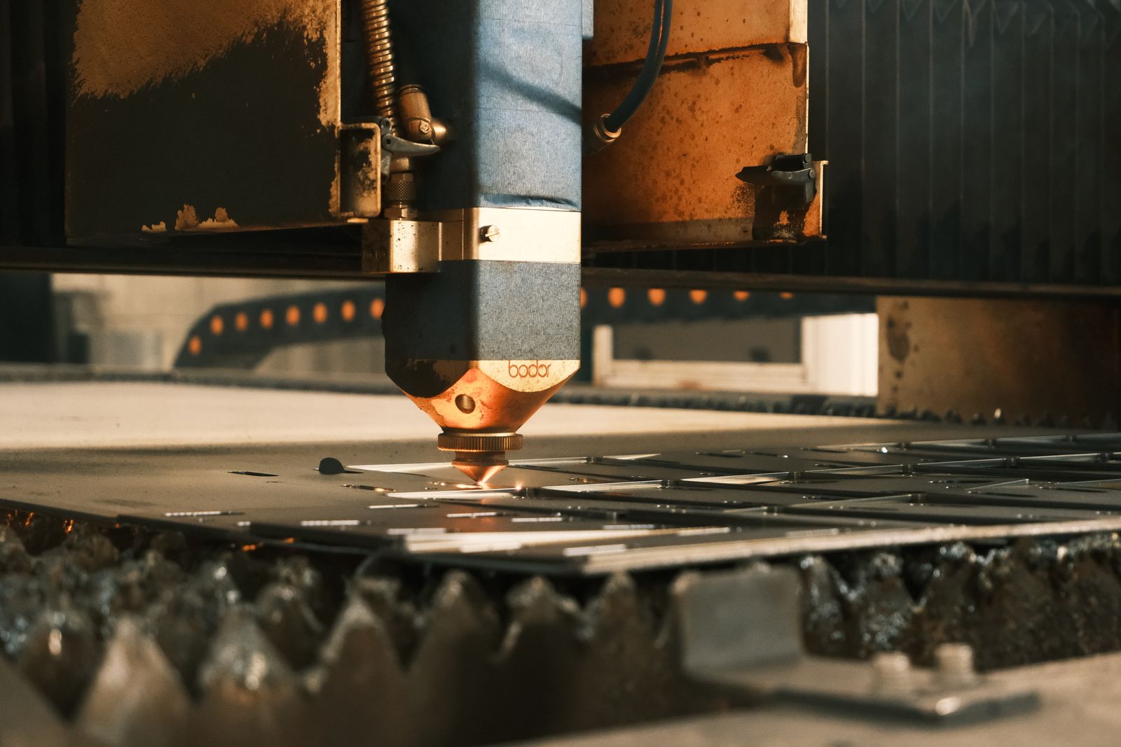
Laser cutting uses a focused laser beam to heat and locally melt or vaporize material along a programmed contour. Cutting gas helps remove the melt from the kerf. It is commonly used to create profiles, holes, slots, tabs, and nested sheet components before forming, welding, machining, or assembly.
Process route
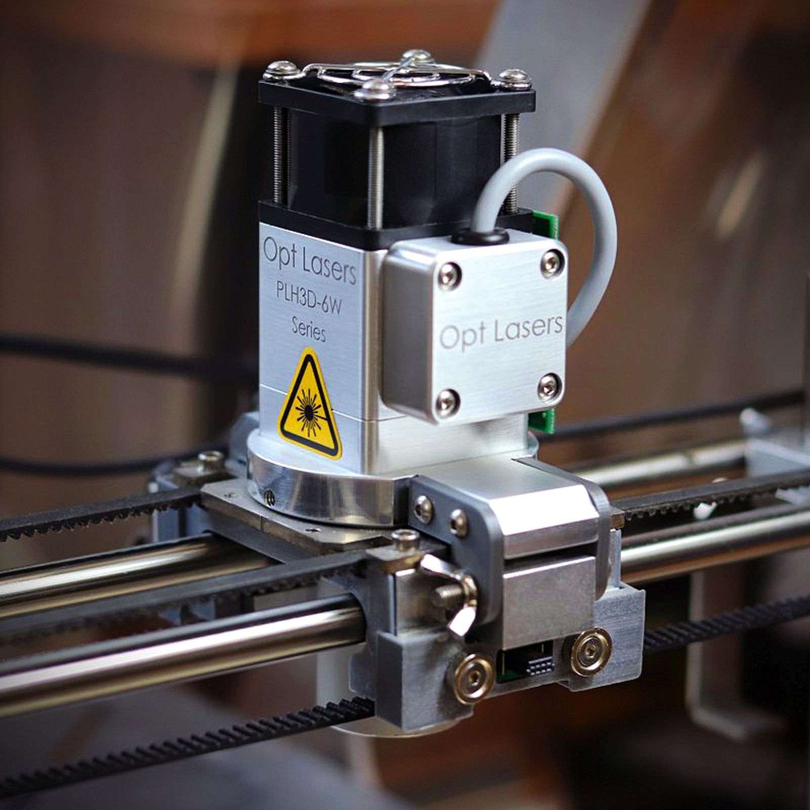
A route starts with a flat pattern, material and thickness selection, nesting, programmed cut order, pierce locations, and edge-condition requirements. The final sequence may include deburring, forming, welding, tapping, machining, coating, or inspection of critical dimensions.
Design input | Why it changes the outcome |
|---|---|
Material and thickness | Common sheet materials include mild steel, stainless steel, aluminum, and selected non-metal materials depending on the laser technology. Material thickness, reflectivity, film, finish, and downstream fabrication must be disclosed. |
Profile and small features | Typical features include external contours, apertures, slots, internal profiles, tabs, louvers where process-supported, small holes appropriate to material thickness, and part-identification marks. |
Downstream operation | Bending, welding, machining, coating, and assembly can change the most suitable cutting route. |
Inspection and acceptance
Quality checks often consider overall profile, hole and slot locations, kerf-related edge condition, heat effect, flatness, burr, and fit with bent or assembled components.
Important: A profile may meet its nominal 2D dimensions and still need a defined plan for burr, taper, heat effect, flatness, protective film, or later edge preparation.
When Laser is the Best Route
Choose laser cutting for programmed sheet contours where thermal cutting is acceptable. Waterjet is a cold-cut alternative for heat-sensitive materials; plasma may be chosen where conductive material and a different speed/edge tradeoff fit the job.
RFQ details
Provide flat pattern files, material grade and thickness, bend or weld context, critical dimensions, minimum feature requirements, edge quality expectation, burr requirements, finish, and required quantity.
Quote check: Provide a flat pattern, material grade, thickness, quantity, critical dimensions, edge expectation, and all required secondary operations.
Key Process Parameters
Parameter | Typical Range / Specification |
|---|---|
Cutting technology | Fiber laser for thin-to-medium sheet metal; CO? laser for selected non-metals and thicker plate on request |
Maximum sheet size (fiber) | Up to 4000 — 2000 mm on standard shuttle tables; larger formats on review |
Maximum material thickness (mild steel) | Up to 25 mm practical; 12 – 20 mm is the typical production range |
Maximum material thickness (stainless) | Up to 20 mm; nitrogen-assist recommended for oxide-free cut |
Maximum material thickness (aluminum) | Up to 15 – 20 mm with optimized parameters and nitrogen-assist |
Kerf width | 0.10 – 0.30 mm typical; depends on material, thickness, and assist gas |
Standard dimensional tolerance | ±0.10 mm on features up to 100 mm; ±0.20 mm on features 100 – 500 mm |
Tight tolerance (on request) | ±0.05 mm achievable on thin gauge with stable fixturing and qualified programs |
Minimum hole diameter | Approx. 1— material thickness as a practical limit; — 0.5— thickness with optimized parameters |
Minimum slot width | Approx. 1.2 – 1.5— material thickness |
Maximum part weight | Limited by sheet-handling capacity of the cutting table |
Batch size | 1 – 10,000+ parts; prototype, low-volume batch, and high-volume production runs |
Lead time | 3 – 7 working days for typical parts; high-volume runs scheduled per capacity |
Accepted file formats | DXF, DWG, STEP (2D-flat), IGES, native CAD on request, PDF for reference |
Typical machine platforms | High-power fiber-laser cutting centers, CO? laser systems for non-metals and selected plate |
Materials We Cut
Laser cutting covers the majority of common sheet metals and selected non-metals. Material grade, thickness, surface condition, and downstream forming or welding must be considered when selecting the laser type and assist gas.
- Mild steel: cold-rolled and hot-rolled A36, A572, DC01, SPCC, SS400, S235JR, S355JR up to ~ 25 mm
- Stainless steel: 304 / 304L, 316 / 316L, 321, 310S, 430; 2B, BA, brushed, and mirror finishes on review
- Aluminum: 5052, 6061, 7075 sheet and plate up to ~ 15 – 20 mm
- Galvanized & zinc-coated steel: cold-rolled with zinc or zinc-iron coating, sheet gauges
- Electrical steel: silicon steel for laminations, including coated grades
- Copper & brass: C110, C260, C360 (limited thickness due to reflectivity; reviewed per project)
- Spring steel (limited): 1095, 301, 304 spring temper (thin gauges) for shims and flat springs
- Non-metals (CO? laser): acrylic, polycarbonate, PETG, ABS, wood, plywood, MDF, leather, paper, rubber
Standard Tolerances & Achievable Precision
Standard cut tolerance is ±0.10 mm on small features and ±0.20 mm on features between 100 mm and 500 mm. Process tolerance depends on material thickness, fixturing, and the cut program; thinner gauges and well-supported parts run closer to the tight end of the range.
- Standard tolerance: ±0.10 mm on features up to 100 mm; ±0.20 mm on features 100 – 500 mm
- Large-feature tolerance: ±0.30 mm or ±0.1 % of dimension on features above 500 mm
- On-request tolerance: ±0.05 mm on thin-gauge features with qualified programs and stable fixturing
- Default standard: ISO 2768-m for un-declared dimensions; ISO 2768-c / -f on request
- Geometric callouts: position, profile, and perpendicularity interpreted per ASME Y14.5 / ISO 1101
Quality Control & Inspection
Laser-cut parts are inspected against the cut program, with attention to hole size, slot width, profile dimensions, edge condition, and burr level. Sampling and full-dimensional inspection are both available depending on the run size and part criticality.
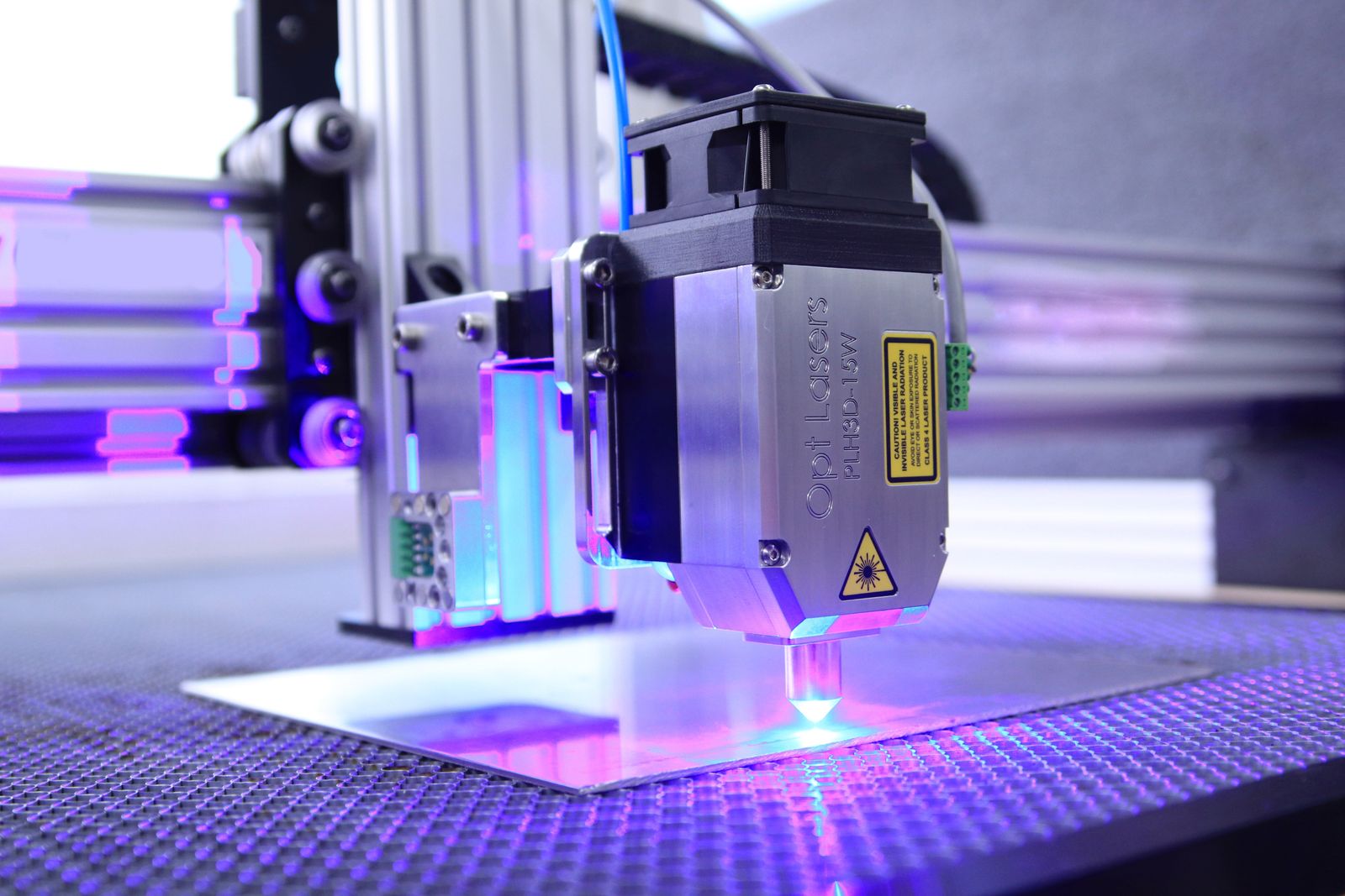
- CMM inspection: bridge-type CMMs for small, high-tolerance parts and critical features
- Optical comparator & vision system: 2D profile measurement for hole size, slot width, and contour
- Surface roughness tester: portable Ra tester for as-cut and post-finish edges where finish is specified
- Calipers, micrometers, pin gauges: hand tools for in-process and first-article checks
- Edge-condition & burr check: visual and tactile inspection against drawing or sample reference
- First-article inspection: full-dimensional report on the first part off the table before run continues
- In-process inspection: periodic checks of critical dimensions, hole size, and edge condition during the run
- Final inspection report: dimensional report, material certificate, and finish confirmation shipped with the parts
Design Considerations (DFM Tips)
- Set hole diameter — material thickness. Smaller holes need higher power, slower speeds, and may burn the entry side; review the ratio before quoting.
- Avoid sharp internal corners. Specify a micro-joint or a small radius (— 0.5— material thickness) on internal corners to avoid overburn.
- Hold tight tolerance to functional features only. Locating holes, mating slots, and weld prep need tighter callouts; cosmetic perimeters can run standard.
- Mind grain direction for formed parts. Major bends perpendicular to the rolling direction are more predictable; communicate forming requirements on the drawing.
- Use tabs and micro-joints on small features that could fall through the slats, or for parts that need to stay aligned during secondary ops.
- Standardize material grade and thickness. Off-standard gauges or grades affect cut speed, edge quality, and nesting; disclose them in the RFQ.
- Disclose coatings, films, or finishes on the incoming sheet (galvanized, anodized, painted, vinyl-clad) since they affect cutting parameters and downstream processing.
- Plan piercing points away from functional edges and away from critical cosmetic faces to avoid visible blemish on the finished part.
- Allow kerf compensation in the part file or on the drawing; the laser kerf removes material that would otherwise change the cut dimension.
- For very thick plate (> 15 mm), review dross level and edge squareness against the drawing requirement; secondary edge finishing may be needed.
What is the smallest hole you can cut?
A practical minimum is approximately 1— the material thickness. Smaller holes are possible with optimized parameters but burn the entry side and reduce accuracy; we recommend punching, drilling, or a reaming step for very small or very high-quality holes.
What files do you need to laser cut a part?
A 2D DXF or DWG of the flat pattern is preferred. STEP 2D-flat, IGES, or native CAD also work. Include material grade, thickness, quantity, bend / weld / hardware context, and any critical dimensions or finish requirements on the drawing.
How to Get a Quote
To quote a laser-cutting job, send the 2D flat pattern (DXF / DWG / STEP), material grade and thickness, batch quantity, any required edge or surface finish, downstream operations (forming, welding, hardware insertion), critical dimensions, and inspection expectations.
You will receive a DFM review with comments on hole / slot feasibility, nesting, kerf and tolerance, and any suggested refinements, followed by a written quote that lists lead time, unit price, finish options, and inspection report scope.
Process Flow & Manufacturing Sequence
Laser cutting follows a defined sequence from file preparation to final inspection. The route is built around the flat pattern, material and thickness, nesting, pierce order, and downstream operations (forming, welding, hardware insertion). Each step below is a discrete production operation with its own setup, parameter library, and inspection checkpoint.
- File preparation & DFM review. 2D flat pattern is received in DXF, DWG, STEP, or native CAD. The pattern is checked for closed contours, layer assignments, scale, and any kerf allowance the customer has already applied.
- Material selection & receipt. Material grade, thickness, surface condition (mill finish, galvanized, brushed, BA, 2B), and protective film are confirmed against the purchase order and material certificate.
- Nesting & cut program. Parts are nested on the sheet to optimize material yield. The cut program defines cut order, pierce points, lead-ins / lead-outs, micro-joints, and any tabs needed for downstream handling.
- Parameter selection. Cutting parameters (power, speed, focus position, assist gas, pressure, nozzle diameter) are selected from the parameter library for the material, thickness, and quality target.
- Sheet loading & squaring. The sheet is loaded on the shuttle table, squared against mechanical stops, and the program origin is established. For high-volume runs, an automatic loading system may be used.
- Focus & nozzle check. The cutting head is checked for focus height, nozzle alignment, and lens cleanliness. Nozzle condition is verified against cut-time or hours of use.
- Pierce & cut. The first part is cut and inspected before the program continues to the rest of the sheet. Pierce points are placed on the scrap side of the line, away from functional or cosmetic features.
- Slug / part removal. Internal slugs fall through the slats to a collection bin. Cut parts are unloaded, separated from the skeleton, and placed in a parts bin. Skeleton (skeleton plate) is removed for recycling or for the next program.
- Edge deburr & clean. Parts are deburred by mechanical means (brush, vibratory, or hand) to break sharp edges and remove any light dross. Protective film is removed if specified by the customer.
- In-process inspection. First article and in-process checks are performed on hole size, slot width, contour dimensions, edge condition, and burr level against the drawing or sample reference.
- Downstream operations (if required). Parts that require forming, welding, hardware insertion, tapping, or machining are routed to the next cell with masking on critical surfaces where applicable.
- Surface treatment (if required). Parts that need powder coat, liquid painting, plating, anodizing, or other finishes are sent to approved partners with masking on critical edges or features as defined by the drawing.
- Final inspection & documentation. Full-dimensional report against the drawing, material certificate, finish confirmation, and any required FAI or PPAP documentation are compiled for shipment.
- Packaging & shipping. Parts are stacked with interleaving paper or foam, then packaged in boxes, cartons, or crates. Sharp edges are protected, and parts are labeled per the program labeling scheme.
Material Property Reference
Material selection for laser cutting is driven by sheet thickness, grade, surface condition, downstream operations, and the cosmetic or functional requirements of the cut edge. The table below lists typical materials with representative mechanical and physical properties used as starting points for DFM review.
Material | Density (g/cm?) | Tensile Strength (MPa) | Yield Strength (MPa) | Hardness (HB) | Laser Compatibility |
|---|---|---|---|---|---|
Mild steel A36 / DC01 / SPCC | 7.85 | 365 – 510 | 210 – 250 | 100 – 150 | Excellent (fiber, O?) |
Stainless 304 / 304L (2B) | 8.00 | 515 | 205 | 202 | Excellent (N? for oxide-free) |
Stainless 316 / 316L (2B) | 8.00 | 485 | 170 | 217 | Excellent (N? for oxide-free) |
Stainless 430 (BA) | 7.75 | 450 | 205 | 183 | Good (fiber) |
Aluminum 5052-H32 | 2.68 | 230 | 195 | 60 | Good (N?, fiber) |
Aluminum 6061-T6 | 2.70 | 310 | 276 | 95 | Good (N?, fiber) |
Galvanized steel (G60, G90) | 7.85 | 365 – 510 | 210 – 250 | 100 – 150 | Good (N? to limit zinc vapor) |
Electrical steel (silicon, M19 – M47) | 7.65 | 370 – 480 | 230 – 320 | 120 – 180 | Good (fiber, coated grades) |
Copper C110 (sheet) | 8.96 | 220 | 70 | 50 | Limited (reflective; thin only) |
Brass C260 (sheet) | 8.53 | 300 – 450 | 100 – 380 | 55 – 130 | Limited (reflective; thin only) |
Acrylic (cast, extruded) | 1.18 | 70 | – | – | Good (CO? laser) |
Plywood / MDF | 0.65 – 0.80 | 30 – 60 | – | – | Good (CO? laser) |
Polycarbonate (PC) | 1.20 | 65 | – | – | Good (CO? laser, edge clarity) |
Cost Drivers & Lead Time Factors
Cost and lead time for laser cutting are driven primarily by material thickness and grade, total cut length, number of pierces, hole count and size, edge-quality requirement (oxide-free N? vs. standard O?), and any required downstream operations (deburring, forming, welding, hardware insertion, finishing). Thicker material and tighter tolerance slow cut speed and increase cycle time. Material utilization (nesting) is a major cost factor at high volume; off-standard gauges or grades affect cut speed and edge quality. The table below summarizes typical lead times for common scenarios.
Scenario | Material Lead Time | Cutting Lead Time | Total (working days) |
|---|---|---|---|
Prototype from stock sheet (1 – 5 parts) | 1 – 3 days | 1 – 3 days | 2 – 5 days |
Low-volume batch (10 – 100 parts) | 2 – 5 days | 2 – 4 days | 3 – 7 days |
Thick plate (10 – 25 mm) — small batch | 3 – 7 days | 3 – 5 days | 5 – 10 days |
High-volume production (1,000+ parts) | 5 – 10 days | 5 – 15 days | 10 – 20 days |
N?-assist stainless (oxide-free cut) | as above | slightly longer | + 0 – 2 days |
Cutting + forming + welding package | as above | + 3 – 7 days | + 3 – 7 days |
Surface treatment (powder, paint, plating, anodize) | as above | + 3 – 7 days | + 3 – 7 days |
Recurring batch with stock material | 0 – 2 days | 2 – 5 days | 2 – 5 days |
Common Defects & Prevention
Defects on laser-cut parts usually trace back to wrong parameter selection, focus drift, nozzle wear, or material condition. The table below lists the most common defects and the prevention strategies we apply in production.
Defect | Cause | Prevention |
|---|---|---|
Dross / slag adhesion on bottom edge | Cutting speed too high, low power, focus position wrong, low assist-gas pressure | Tune parameters from the material library, verify focus and nozzle, increase assist-gas pressure, slow down for thick plate, re-cut the affected part |
Excessive heat-affected zone (HAZ) | Cutting speed too low, power too high, dull nozzle | Use qualified parameter set, replace nozzle on schedule, increase speed within the quality window, switch to fiber laser for thin-to-medium steel |
Taper on thick plate | Beam divergence through thickness, focus offset, single-pass cutting | Set focus to mid-thickness for thick plate, use higher-power source, switch to waterjet for very thick plate or zero-taper requirement |
Wide or inconsistent kerf | Dull nozzle, wrong focus, material inconsistency, beam misalignment | Replace nozzle on schedule, calibrate focus per shift, verify incoming material certificate, periodic beam alignment |
Warping of thin sheet | Excessive heat input, asymmetric pattern, unsupported sheet, sharp corners | Use micro-joints to keep parts in the sheet, balanced nesting, support slats set close, slow down for thin gauge, add tabs and corners |
Micro-cracking on hard or brittle material | High thermal gradient, hard / brittle grade, thick section | Switch to waterjet for brittle materials, lower cutting speed, use pulse-mode cutting, or pre-heat the sheet for hard grades |
Slag adhesion on stainless after N? cut | Insufficient N? pressure, focus drift, contamination in nozzle | Verify N? pressure and purity, clean nozzle, re-check focus, tune to certified parameter set for oxide-free cut |
Burr formation at entry / exit edges | Wrong pierce point, focus at exit, low pressure | Pierce in scrap, set focus to mid-thickness, increase pressure, follow with deburr or chamfer-mill on cosmetic edges |
Comparison With Related Processes
Laser cutting is often selected alongside or in place of waterjet, plasma, CNC routing / engraving, and turret punching. The table below compares the four most common alternatives for sheet and plate contour work.
Aspect | Laser Cutting | Waterjet Cutting | Plasma Cutting |
|---|---|---|---|
Cutting mechanism | Focused laser beam with assist gas | High-velocity water with optional abrasive | Electric arc through assist gas |
Material thickness | Up to ~ 25 mm mild steel; 15 – 20 mm stainless / aluminum | Up to ~ 150 mm metal; 100 mm stone / glass | Up to ~ 50 mm mild steel; 25 mm stainless / aluminum |
Edge condition | Clean, narrow kerf; small HAZ; light dross on thick plate | Smooth, no HAZ, slight taper on thick plate | Wider kerf, larger HAZ, more dross |
Tolerance band | ±0.10 mm small features; ±0.20 mm mid; ±0.05 mm tight | ±0.10 mm small; ±0.20 mm mid; ±0.05 mm tight | ±0.30 – ±0.50 mm typical; tighter on thin plate |
Material flexibility | Steel, stainless, aluminum, brass (thin), non-metals (CO?) | All metals, stone, glass, ceramic, composites, plastics | Steel, stainless, aluminum (limited non-metals) |
When to choose | Thin-to-medium sheet, tight tolerance, high-volume production | Thick plate, heat-sensitive materials, composites, stone / glass | Thick mild steel, lower cost, looser tolerance |
Industry Standards & Certifications
- ISO 9001:2015 — Quality management system requirements; baseline certification for our production control
- AS9100D — Aerospace quality management system; applied to flight-critical sheet metal components
- ISO 13485:2016 — Medical device QMS; applied to medical enclosures and equipment panels
- IATF 16949 — Automotive QMS; applied to chassis, body, and EV components
- RoHS & REACH — Restriction of hazardous substances and chemical substances; applied to material selection and surface treatment
- ITAR — U.S. International Traffic in Arms Regulations; applied to defense-related sheet components under controlled programs
- ISO 2768 — General tolerances for linear and angular dimensions (medium, fine, coarse classes)
- ASME Y14.5 / ISO 1101 — Geometric dimensioning & tolerancing; GD&T interpretation on drawings
- ISO 5459 — Datums and datum systems; used to define flatness and profile datums on sheet patterns
- AWS D1.1 / D1.2 / D1.3 — Structural welding code (steel, aluminum, sheet steel); applied to welded sub-assemblies
- ASTM A967 — Chemical passivation treatments for stainless steel parts
- NFPA T3.8.1 / ISO 4413 — Hydraulic safety and fluid power; applied to waterjet / laser assist gas system safety
- PPAP / FAI per AIAG — Production part approval process and first-article inspection per automotive and aerospace practice
Packaging, Shipping & Documentation
Laser-cut parts are packaged to protect edges, cosmetic surfaces, and protective film (where the customer has specified that the film stay in place through delivery). Parts are stacked with interleaving paper or foam, then packaged in boxes, cartons, or crates depending on part size and quantity. Standard documentation is shipped with the parts; additional documents (PPAP, FAI, signed drawings) are provided per program requirement.
- Cleaning & protective film. Parts are cleaned of debris and cutting residue. Protective film supplied on the original sheet is preserved through the cutting and packaging stages when the customer requires it.
- Edge & surface protection. Edges are protected with foam strips, edge guards, or interleaving paper. Cosmetic surfaces (brushed, mirror, BA) are protected from contact damage.
- Stacking & interleaving. Flat parts are stacked with paper or foam interleaving to prevent contact damage. Heavy parts are individually wrapped and labeled.
- Box, carton, & crate selection. Small parts are packed in labeled boxes; medium parts in heavy-duty cartons; large or heavy parts in custom crates with lift points.
- Labeling & traceability. Each carton is labeled with part number, batch, quantity, and program ID per the program labeling scheme. Inner packs are individually labeled for downstream assembly.
- Shipping options. Standard road freight for domestic; sea freight (FCL / LCL) for export; air freight for time-critical or high-value parts. Incoterms 2020 (EXW, FOB, CIF, DAP, DDP) applied per the quote.
- Standard documents. Certificate of Conformance (C of C), Material Test Certificate (MTC / mill cert), dimensional inspection report, and surface-finish confirmation.
- FAI report. First-article inspection report against the drawing or 3D model, including all GD&T callouts and datum references, on the first part of each lot.
- PPAP & control plans. Available for automotive and aerospace programs per AIAG / AS9100 requirements.
- Traceability. Heat number, batch number, and operator / machine ID retained for full traceability per the program quality plan.
- Digital delivery. Inspection reports, FAI, and material certificates can be delivered as signed PDFs, with cut program and nesting files on request.
Related Capabilities & Cross-Services
Laser cutting is most often the first step in a sheet-metal fabrication package. The capabilities below are commonly combined with laser cutting to deliver a finished part or sub-assembly.
- CNC press-brake forming — for bends, hems, channels, and complex formed geometry on cut blanks
- MIG / TIG welding — for welded sub-assemblies, brackets, and frames produced from cut parts
- Hardware insertion & PEM stud welding — for self-clinching fasteners, studs, and standoffs installed before or after forming
- Tapping & drilling — for threaded or clearance holes where the laser cannot achieve the diameter or quality
- CNC machining — for thick plate parts that need additional milled features after cutting
- Deburring & edge finishing — mechanical, vibratory, or hand deburr plus chamfer / edge break per the drawing
- Surface treatment — powder coat, liquid painting, anodizing (Type II / III), electroplating (zinc, zinc-nickel, tin, nickel), passivation, and black oxide
- Laser marking & engraving — for permanent part numbers, logos, and traceability marks on functional or visible surfaces
- Plasma & waterjet cutting — for thick plate and exotic materials where laser is not the best fit; offered as part of a multi-process package
- Sheet-metal assembly — for full sub-assemblies including hardware, gaskets, labels, and packaging
Kerf, Burr, and Secondary Fabrication
Specify whether parts require deburring, protective film retention, brushing, coating, bending, welding, threaded inserts, or hardware installation after cutting.
Laser cutting produces programmed sheet profiles with downstream forming, welding, or assembly in mind.
Where the route adds value
Applications include enclosures, machine guards, electronics, brackets, industrial equipment, automotive and transport parts, architectural components, and prototype sheet-metal work.
Question | Decision consequence |
|---|---|
Is heat effect acceptable? | Directs the choice between thermal and cold-cutting routes. |
Is the part finished after cutting? | Determines the needed edge condition and tolerance strategy. |
Will it be formed or welded? | Changes nesting, grain/film handling, and location of critical dimensions. |
Surface Finish Options
As-cut laser edges meet many functional requirements and are often ready for downstream forming, welding, or assembly. Secondary finishes address corrosion, cosmetic appearance, and edge condition.
- As-cut: standard laser-cut edge, light dross and heat tint on thicker steel
- Deburred edge: mechanical or vibratory deburring for clean handling and downstream fit
- Edge-ground / chamfered: light edge grind or chamfer for mating surfaces, weld prep, or cosmetic appearance
- Bead blast: matte texture on visible cosmetic surfaces
- Brushed / grained: directional finish on stainless and aluminum cosmetic surfaces
- Anodize Type II: aluminum parts, standard or custom color
- Powder coat: polyester or epoxy powder over chemical or blast pretreatment, RAL / Pantone match
- Liquid painting: primer + topcoat systems, custom colors, including wet-on-wet for high-volume parts
- Electroplating: zinc, zinc-nickel, tin, or nickel for corrosion protection on steel sheet
- Passivation: citric or nitric passivation for stainless steel after cutting per ASTM A967
- Black oxide: mild corrosion resistance and appearance for steel parts
- Laser marking / engraving: permanent part numbers, logos, and traceability marks on functional or visible surfaces
Can you laser cut stainless without discoloration?
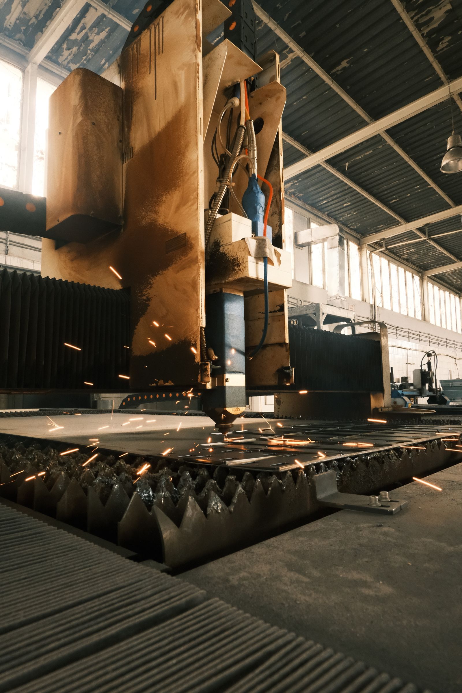
Yes, using nitrogen-assist cutting on stainless produces an oxide-free, bright cut edge. This is a standard option for parts that need to pass corrosion or passivation tests without post-cut edge treatment.
Do you offer forming, welding, or finishing after cutting?
Yes. We offer CNC press-brake forming, MIG / TIG welding, hardware insertion, deburring, and the surface finishes listed above. A complete fabrication RFQ usually quotes cutting plus the required downstream operations in one package.
- Enclosures and covers
- Brackets and machine guards
- Sheet-metal panels and frames
- Electrical and electronics housings
- Prototype sheet-metal components
Laser-Cut Part Families
Typical components include brackets, enclosures, covers, guards, panels, plates, frames, machine parts, electrical housings, and custom sheet-metal assemblies.
Industries & Applications
- Automotive: brackets, chassis reinforcements, mounting plates, battery enclosures, EV components
- Industrial machinery: machine guards, panels, frames, covers, equipment enclosures
- Electronics & electrical: enclosures, rack panels, control panels, chassis, busbars
- HVAC & building: duct components, brackets, ventilation parts, architectural panels
- Signage & displays: lettering, decorative panels, custom signage, retail displays
- Furniture & lighting: metal furniture parts, lighting fixtures, decorative panels
- Renewable energy: solar racking, inverter brackets, battery storage components
—
How accurate is laser cutting on large flat patterns?
For 2D patterns within the table, accuracy is typically ±0.10 mm on small features and ±0.20 mm on features between 100 mm and 500 mm. Patterns with critical hole-to-hole patterns are quoted with the actual achievable tolerance rather than a single number across the whole sheet.

