

Engineering question
What must work when the part is real?
Tool Access, Burrs, and Workholding
Typical features include small holes, micro slots, miniature threads, fine grooves, thin walls, small radii, connector interfaces, precision pins, and compact internal passages.
Typical part context
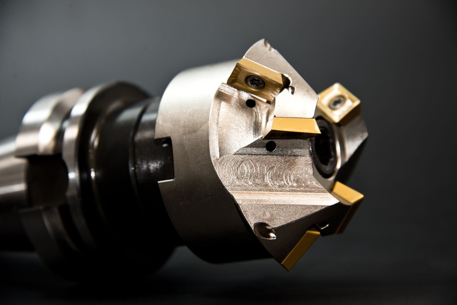
Common components include sensor housings, electrical contacts, precision pins, optical mounts, miniature medical-device parts, micro-fluidic hardware, small fixtures, and electronics interfaces.
Frequently Asked Questions
How small a wall or feature can you hold?
0.05 mm walls are achievable on stainless, titanium, and PEEK with micro-milling or micro-EDM. Below that, we recommend laser or wire EDM depending on geometry.
Feature size | Miniature features, thin walls, and small radii |
|---|---|
Tooling | Short rigid tools with controlled cutting conditions |
Inspection | Optical, microscope, pin gauges, or specialized probes |
Typical use | Sensor housings, medical micro parts, optical and electronics interfaces |
What tolerances can you hold on micro features?
±0.005 mm on critical features is realistic for production. ±0.0025 mm is achievable with CMM-verified process. For true gauge-grade features, we add micro-grinding or lapping.
Micro Machining Services
A source-aware reference guide to miniature features, tool access, burr control, inspection planning, and material-aware micro machining.
Primary concern Identify the smallest critical features, required edge condition, surface finish, allowable burr, measurement datum, and any part areas that cannot be touched or clamped. Avoid assuming that all small details are automatically manufacturable. | Validation lens Inspection must suit the size of the feature and may require optical methods, microscopes, pin gauges, specialized probes, or functional checks. The acceptance criteria should be stated in a measurable form. |
|---|
This page uses a design-review opening so the service reads like an engineering brief rather than a repeated product brochure.
What is the part proving?
Micro machining can create functional metal or plastic components with detailed features while retaining the material properties needed for the final application.
Design question | Review before machining |
|---|---|
Which feature controls function? | Identify the smallest critical features, required edge condition, surface finish, allowable burr, measurement datum, and any part areas that cannot be touched or clamped. Avoid assuming that all small details are automatically manufacturable. |
What is a successful output? | Inspection must suit the size of the feature and may require optical methods, microscopes, pin gauges, specialized probes, or functional checks. The acceptance criteria should be stated in a measurable form. |
Material decision
Materials can include aluminum, stainless steel, brass, copper alloys, titanium, engineering plastics, and specialty metals. Chip behavior, burr formation, thermal movement, and workholding response are especially important at small scale.
Design signal: Make critical datums, small or delicate features, and finish-sensitive areas explicit. They should drive the process, not appear as a late exception.
Microscale Inspection and Part Protection
The process starts with a model and drawing review, then selects stable workholding, short tools, controlled cutting conditions, deburring approach, and inspection method. Machining often proceeds from more rigid datum features to delicate details so that the part remains supported as long as possible.
When another route may be better
Choose micro machining when the final material and precision features matter. Alternative processes may be considered for geometries that are better formed, etched, molded, or additively manufactured.
RFQ check: Include the job's true objective: fit check, material test, production release, pilot quantity, inspection record, or a combination of these.
Materials We Machine
- Stainless steels – 303, 304, 316L, 17-4 PH, 420, 440C for micro-medical and micro-fluidic parts.
- Titanium alloys – Grade 2, Grade 5 (Ti-6Al-4V), Grade 5 ELI for implants and surgical instruments.
- Hardened tool and die steels – D2, M2, SKD11 up to 62 HRC (typically via micro-EDM).
- Aluminum alloys – 6061, 7075, 2024 for micro-optics and electronics housings.
- Copper and brass – C110, C101, C360 for electrical contact features and thermal parts.
- Beryllium copper (C17200) – for spring contacts and instrument components.
- Engineering plastics – PEEK, Torlon, Vespel, Delrin, PEI (Ultem), PPSU, medical-grade polycarbonate.
- PTFE and other fluoropolymers – for fluidic and chemical-resistance micro parts.
- Technical ceramics and glass – alumina, zirconia, fused silica (via micro-grinding / laser).
- Carbide and graphite preforms – micro-EDM shaping for cutting tools and EDM electrodes.
What is the smallest hole you can machine?
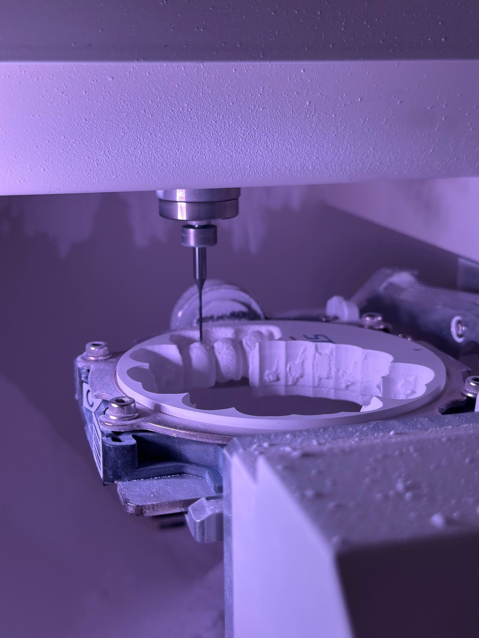
0.1 mm with micro drills, 0.05 mm with micro-EDM, and 0.025 mm or smaller with femtosecond or UV laser. We choose the process based on material, depth, and tolerance.
Can you do micro-EDM and laser cutting in-house?
Yes. We use micro-EDM for hardened steel and carbide, and femtosecond / UV laser for ultra-fine features, ceramics, and selected polymers. The right process is selected based on the geometry, material, and tolerance.
Do you handle medical-grade materials and documentation?
Yes. We work with medical-grade stainless, titanium (Grade 5 ELI), PEEK, and PPSU. Material traceability, certificates of conformance, and biocompatibility-related documentation are available on request.
How to Get a Quote
Send your 3D CAD file (STEP, IGES, X_T, or native), 2D drawing with GD&T, material grade, lot size, target tolerances, surface finish, and any coating or post-process requirements. For very small features, include a microscope image or a sample part if available. We return a DFM review on process selection (micro-mill vs. EDM vs. laser), a lead time for prototype and production, and a unit price that includes material, machining, inspection, and finishing.
Process Flow & Manufacturing Sequence
Micro-machining is the controlled application of precision cutting, micro-EDM, and laser micro-processing to features that are typically smaller than 1 mm. The sequence below describes the typical route for a miniature metal or plastic part with multiple small features.
- Feature review and process mapping – Each micro feature (small hole, slot, wall, or corner) is mapped to a process (micro-milling, micro-drilling, micro-EDM, or laser). The smallest tool, the achievable tolerance, and the inspection method are confirmed before quoting.
- Material selection and stock prep – Pre-sized blanks or short bar stock are used to keep the part rigid. Stress-relieved or annealed material is preferred for plastic-prone alloys (e.g. titanium, 17-4 PH) to limit burr and distortion.
- Substrate cleaning and fixturing – Aqueous clean and dry before fixture loading. Micro parts are commonly fixtured in a custom ground soft-jaw nest, vacuum chuck, or wax/polymer mount.
- Machine selection – High-resolution 3-axis / 5-axis precision platform with linear scales, thermal compensation, and a vibration-isolated foundation. Spindles selected for the rpm range required by the smallest tool.
- Tool selection and verification – Micro end mills (50–200 —m), micro drills (50–500 —m), or custom single-point cutters. Tool runout checked at the holder, often with a tool presetter or laser inspection.
- Rough micro-machining – Trochoidal or adaptive strategies with low radial engagement; chip thinning is monitored, and chip evacuation is critical to avoid recutting.
- Semi-finish micro-machining – Light radial passes bring features within 5–10 —m of target, leaving controlled stock for finishing.
- Finish micro-machining – Single-pass finishing at low feed, sharp tool, light cut. Surface roughness typically 0.2–0.4 —m Ra on metal, 0.4–0.8 —m on plastic.
- Micro-EDM (when required) – Wire EDM for through-slots, micro holes, and small corner radii. Sinker EDM for micro cavities and sharp internal corners in hardened steel or carbide.
- Laser micro-processing (when required) – Femtosecond or UV laser for sub-25 —m features, micro holes, or polymer ablation. Used where mechanical access is impossible.
- Deburr and edge conditioning – Tumble with fine media, electrochemical deburr, or hand-deburr under microscope. Aggressive mechanical deburr is avoided because it can chip micro walls.
- Cleaning and surface prep – Multi-stage aqueous or semi-aqueous clean. Micro-fluidic parts may require ultrasonic cleaning and DI rinse.
- Surface finishing – Electropolish for stainless steel micro parts, micro-passivation, anodize, or parylene coating depending on the application.
- Inspection – Optical / video measurement system, scanning electron microscope (SEM) for sub-10 —m features, white-light interferometer for surface finish, and pin gauges for slot/hole size.
- Marking, packaging, and release – Laser marking on a designated area; clean-room bagging for medical / semiconductor parts; full documentation released with shipment.
Material Property Reference
Reference property values for materials commonly run as micro-machined parts. Density is in g/cm?. Machinability references AISI 1212 at 100%; lower values typically mean more rigid setups, micro-tooling wear, and burr-management attention.
Material | Density (g/cm?) | Tensile Strength (MPa) | Yield Strength (MPa) | Hardness | Machinability Rating (%) |
|---|---|---|---|---|---|
Stainless 304 (annealed) | 8.00 | 620 | 290 | 180 HB | 45 |
Stainless 316L (annealed) | 8.00 | 560 | 290 | 170 HB | 40 |
Stainless 17-4 PH (H900) | 7.78 | 1380 | 1280 | 420 HB | 40 |
Stainless 440C (HRC 58) | 7.65 | 1750 | 1650 | 580 HV | 30 (EDM preferred) |
Titanium Grade 2 | 4.51 | 345 | 275 | 200 HB | 40 |
Titanium Grade 5 (Ti-6Al-4V) | 4.43 | 950 | 880 | 335 HB | 22 |
Titanium Grade 5 ELI | 4.43 | 860 | 795 | 320 HB | 24 |
Aluminum 6061-T6 | 2.70 | 310 | 276 | 95 HB | 180 |
Aluminum 7075-T6 | 2.81 | 572 | 503 | 150 HB | 170 |
Copper C110 (ETP) | 8.94 | 220 | 70 | 50 HB | 20 |
Beryllium copper C17200 (aged) | 8.36 | 1310 | 1140 | 350 HB | 20 |
Tool steel D2 (Q&T 60 HRC) | 7.70 | 1860 | 1650 | 620 HV | 25 (EDM) |
PEEK (unfilled) | 1.30 | 100 | — | M99 (Rockwell) | — (sharp tooling) |
PEEK (30% carbon fiber) | 1.40 | 240 | — | M100 (Rockwell) | — (abrasive) |
Cemented tungsten carbide (10% Co) | 14.5 | 1500 | — | 1500 HV | — (EDM / grind) |
Cost Drivers & Lead Time Factors
Micro-machining cost and lead time depend on the smallest feature, the inspection method, and the part quantity. A single 0.05 mm micro hole can take longer than several millimeters of conventional drilling. The table below summarizes realistic timelines.
Scenario | Quantity | Typical Lead Time | Primary Cost Drivers |
|---|---|---|---|
Stainless micro-fluidic manifold prototype | 1–3 off | 2–3 weeks | Custom tooling, micro-EDM prep, microscope inspection |
Titanium surgical instrument blanks | 5–20 off | 3–4 weeks | Material, low MRR, electropolish, FDA traceability |
Aluminum sensor housing, ±0.0125 mm | 20–100 off | 2–3 weeks | Setup, anodize mask, optical inspection |
PEEK micro-fluidic chip | 5–25 off | 2–3 weeks | Tool wear on abrasive plastic, microscopy inspection |
Carbide cutting tool insert, micro-EDM | 50–500 off | 3–5 weeks | Wire EDM time, electrode cost, breakage allowance |
Stainless 316L medical implant, ISO 13485 | 10–50 off | 4–6 weeks | Validated process, clean packaging, full certs |
Beryllium copper spring contact, laser cut | 1,000–10,000 off | 3–4 weeks | Tooling setup, fixturing for batch, plating |
Sub-25 —m laser features on polymer | any | +1–2 weeks vs standard | Femtosecond / UV laser, optical profile metrology |
Common Defects & Prevention
Defect | Cause | Prevention |
|---|---|---|
Micro-tool breakage | Excessive tool overhang, chip packing, wrong cutting parameters, runout at the spindle, material inclusions | Use balanced toolholders (shrink-fit or hydraulic), set max-engagement strategies, run vibration-damped spindles, document tool-life and replace proactively |
Burr on micro walls, holes, and slots | Dull tool, exit-side tear, no chamfer, aggressive material | Sharp polished micro tools, ramp-on entry, light finishing pass, controlled deburr (electrochemical or fine-media tumble) |
Micro-hole taper or bell-mouthing | Drill wander, runout, chip evacuation problem, drill geometry not matched to material | Peck-drill cycle, pre-spot with EDM, use guided micro drills, run at proper rpm for the diameter |
Inconsistent feature size lot-to-lot | Tool wear, fixturing repeatability, stock hardness variation, thermal drift in machine | Track tool wear on pilot parts, use a calibrated fixture with datum pins, control shop temperature ±1 —– |
Heat-affected zone (HAZ) on laser-cut edges | Wrong pulse duration or power, single-pass cut on thick section, no gas assist | Use femtosecond or UV laser for low HAZ, multi-pass with optimized parameters, add assist gas if burr-free edge is required |
Chip re-cutting and recast layer (EDM) | Insufficient flush, wrong pulse settings, deep cavity without electrode drop, broken wire | Optimize flush nozzles, multi-cut strategy with skim passes, monitor wire condition, control recast to <5 —m for medical parts |
Part deflection under cutting force | Thin walls, weak fixture, heavy cut, wrong tool geometry | Use balanced cuts, light finishing, back-side support during roughing, or design-in sacrificial material |
Inspection miss or false accept | Wrong measurement method, inadequate resolution, lighting issue on optical system, no calibration traceable to national standard | Use optical / video measurement with calibrated stage, white-light interferometer for surface, SEM for sub-10 —m, calibrated pin gauges for slot width |
Comparison With Related Processes
Aspect | Micro Machining | Alternative | When to Choose |
|---|---|---|---|
Smallest feature size | 0.05 mm wall / 0.02 mm slot on milling; 0.1 mm hole on drilling | Femtosecond laser: 0.005 mm kerf; micro-EDM: 0.03 mm wire diameter | Choose laser/EDM for sub-50 —m features and sharp inside corners; milling for accessible micro features |
Hard-material capacity | Up to 60 HRC with micro-EDM; milling limited to ~58 HRC | Wire EDM: any conductive material regardless of hardness | Choose EDM for carbide or hardened micro features; micro-milling for softer alloys |
Throughput | Slower per feature; cycle times scale with tool changes and inspection | MIM / micro-MIM: very high volume once tooling is cut | Choose MIM for 50k+ parts with stable geometry; machining for low-to-medium volume and rapid iteration |
Surface integrity on metal | Compressive residual stress possible; burr-free with sharp tools | EDM: recast layer, possible micro-cracks; laser: HAZ if not femtosecond | Choose micro-machining for fatigue-loaded medical or aerospace micro features |
Material flexibility | Wide range: stainless, titanium, aluminum, plastic, copper, brass | Lithium disulfide / other exotic 2D materials, ultra-thin films | Choose micro-machining for bulk metallic and plastic micro parts; laser for exotic 2D materials |
Packaging, Shipping & Documentation
Micro parts are usually small, expensive, and easy to damage. Packaging isolates them from contact, ESD, and contamination, with documentation scaled to the regulatory scope.
- Anti-static packaging – Static-shielding bags and pink anti-stat foam for any electronic or semiconductor micro parts.
- Clean-room bagging – ISO 7 / ISO 8 clean-room bags heat-sealed for medical implants and semiconductor micro parts.
- Custom machined tray – CNC-machined plastic or aluminum tray with cavities per part, used for high-value medical and aerospace parts.
- Glass vial / tube – For small cylindrical micro parts, pins, and contacts.
- Outer carton – Double-wall corrugated with foam-in-place, custom inserts, or foam-in-bag for vibration isolation.
- Labeling – Per-piece label when serialized; outer carton marked with part number, lot, and revision.
- Shipping options – Hand-carry for medical spares, expedited air for short lead times, standard freight for production lots.
- Standard documents – Certificate of Conformance (C of C) keyed to part number and revision.
- Material certificate – MTC or 3.1 / 3.2 inspection certificate per EN 10204.
- Surface-finish certificate – When electropolish, passivation, or plating is in scope.
- First-article report – AS9102 / ISIR with full layout and optical / CMM / SEM images.
- Traceability – Heat number, lot, and machine logs retained for the contracted retention period.
Miniature Features and Their Failure Modes
Micro machining applies precision manufacturing methods to parts or features that are small enough for tool size, rigidity, burr formation, surface condition, and inspection access to dominate the plan. The objective is to make the miniature feature functional and measurable, not simply to scale down a conventional machining route.
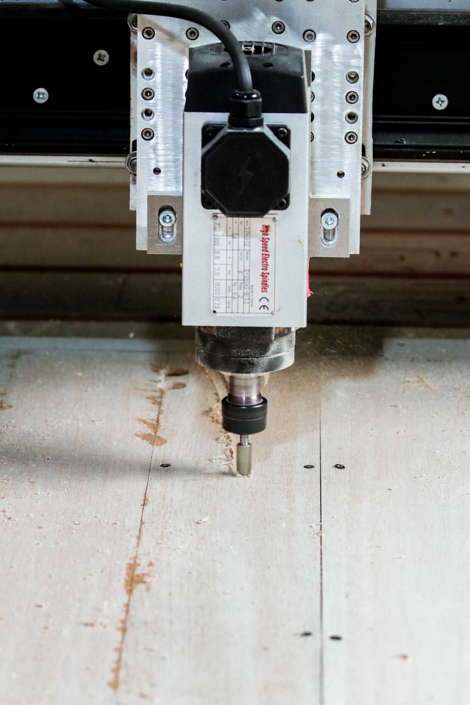
Micro-machining work focuses on miniature features, short tools, and inspection that suits the size of the part.
Key Process Parameters
Parameter | Typical Value |
|---|---|
Min feature size | 0.05 mm wall / 0.02 mm slot on micro-milling; 0.1 mm diameter holes standard, down to 0.05 mm with micro-EDM |
Min hole diameter | 0.1 mm with micro drills, 0.05 mm with micro-EDM, 0.025 mm with femto/UV laser |
Dimensional tolerance | ±0.0125 mm standard, ±0.005 mm precision, ±0.0025 mm ultra-precision |
Positional accuracy | ±0.005 mm true position on critical micro features |
Surface finish Ra | 0.2 —m to 0.8 —m as-machined; 0.05 —m to 0.2 —m after electropolish or micro-finishing |
Max part envelope | Up to 200 mm — 200 mm — 100 mm on desktop-precision platforms; smaller preferred for stiffness and accuracy |
Min corner radius | 0.05 mm with 100 —m end mills; 0.01 mm achievable with micro-EDM |
Min slot width | 0.05 mm (slitting saw or wire EDM); 0.02 mm with femtosecond laser |
Batch range | 1 prototype to 10,000+ pieces (micro-precision production) |
Standard lead time | 7–15 days for prototype, 3–5 weeks for production |
Accepted file formats | STEP, IGES, X_T, SolidWorks native, CATIA, DWG/DXF, PDF drawing |
Typical machines | Precise small-format CNC (Haas Mini Mill, Datron Neo, R?ders RXP), micro-EDM (Sodick, Charmilles), femtosecond / UV laser workstations, high-resolution 3-axis to 5-axis precision platforms |
Standard Tolerances & Achievable Precision
Micro-machining combines precision machine tools, high-resolution motion systems, and specialized processes like micro-EDM and laser ablation. The numbers below are realistic production values, not theoretical limits.
- ±0.025 mm general micro-machining tolerance (ISO 2768-m default).
- ±0.0125 mm tight tolerance on most features with tool-compensated finishing.
- ±0.005 mm precision on critical micro features and reference features.
- ±0.0025 mm ultra-precision on gauge and reference features with CMM verification.
- ±0.001 mm achievable on selected features with micro-grinding or lapping.
- True position 0.005 mm on small holes and slots.
- Surface finish 0.2 —m to 0.8 —m Ra as-machined; 0.05 —m to 0.1 —m Ra after electropolish or micro-finishing.
Surface Finish Options
- As-machined – 0.4 —m to 0.8 —m Ra on stainless and titanium; finer on aluminum and brass.
- Micro-bead blast (fine glass bead) – uniform matte surface, no dimensional change on critical features.
- Electropolish – ASTM B912 on stainless steel to 0.1 —m to 0.2 —m Ra and improved corrosion resistance.
- Passivation – ASTM A967 / A380 after micro-machining.
- Anodize (Type II / Type III) – on aluminum micro-housings, with masking of precision features.
- Electroless nickel (low-phosphorus / mid-phosphorus) – uniform deposit on micro features; controlled thickness.
- Hard chrome – on pre-machined parts with controlled final grind.
- Parylene C / N coating – thin conformal coating for medical and electronics micro parts.
- Black oxide and manganese phosphate – on steel micro components.
- Laser marking – fine ID marks, lot numbers, and scale markings on micro faces and shoulders.
- Polishing and lapping – for optical and sealing faces.
Quality Control & Inspection
Inspection at this scale is specialized. We use high-magnification metrology and micro-feature tooling to verify each part.
- Toolmaker's microscope / digital measuring microscope – for small features down to 0.01 mm.
- CMM with micro-probes and scanning probes – Zeiss, Hexagon, and Renishaw for GD&T and datum alignment.
- Video measuring system (VMS) – non-contact 2D and 3D measurement for small parts.
- Optical profiler / white-light interferometer – for surface finish and step-height on micro features.
- Surface roughness tester – Mitutoyo SJ-series or Mahr for low-Ra verification.
- Micro-hardness tester – Vickers or Knoop on micro-indents and thin features.
- Pin gages and micro-bore gauges – for hole-size and feature verification.
- First-article inspection (FAIR / AS9102 or PPAP) – documented with CMM PDF and microscope captures.
- In-process checks – periodic dimensional verification during production runs.
Design Considerations (DFM Tips)
- Match feature size to process – sub-0.1 mm features usually need micro-EDM or laser rather than conventional micro-milling.
- Keep wall thickness — 0.05 mm where possible – thinner walls are fragile in handling, fixturing, and inspection.
- Use consistent wall thickness – reduces distortion in heat-treat-prone alloys like 17-4 PH and titanium.
- Specify tight tolerances only on functional features – micro tolerances are costly and time-consuming; limit them to features that drive fit or function.
- Avoid deep micro-cavities – 3:1 depth-to-width is a safe rule; deeper cavities may need EDM or laser.
- Add fillets at internal corners – 0.05 mm minimum reduces stress and allows cutter access.
- Provide datum and clamping references – micro parts need a stable reference for both machining and inspection.
- Consider laser or micro-EDM for non-standard features – sharp corners, micro-slots, and ultra-fine holes are often better done with these processes.
- Specify surface finish per feature – a sealing face, a sliding face, and a cosmetic face should be called out separately.
- Plan post-machining processes – electropolish, passivation, and coating can change dimension and finish; design for stock accordingly.
Industry Standards & Certifications
- ISO 9001:2015 – QMS baseline for any job shop running micro features.
- AS9100D – Required for aerospace micro-fluidic, sensor, and instrumentation parts.
- ISO 13485:2016 – Required for medical implants, surgical instruments, and micro-fluidic diagnostic parts.
- IATF 16949 – Used by automotive sensor and connector manufacturers.
- RoHS & REACH – Required for European electronics, consumer, and medical supply chains.
- ITAR – Required for defense and military micro assemblies and sensors.
- ISO 2768-1 / ISO 2768-2 – General tolerance reference for un-toleranced micro features.
- ASME Y14.5-2018 – GD&T applied to micro features, including position, profile, and runout.
- ISO 5459 – Datum reference for inspection of micro features.
- SAE AS9102 – First-article inspection report for aerospace micro parts.
- ISO 10360 – CMM acceptance; for parts small enough that CMM is not appropriate, optical systems calibrated to VDI / VDE 2617 apply.
- ISO 14644-1 – Cleanroom classification for medical and semiconductor micro parts.
- ASTM E2862 – Standard practice for measurement of surface roughness on micro parts using optical profilers.
Related Capabilities & Cross-Services
Micro-machining is often combined with finishing and inspection that match the size of the part. The capabilities below pair naturally with micro-machined parts on the same PO.
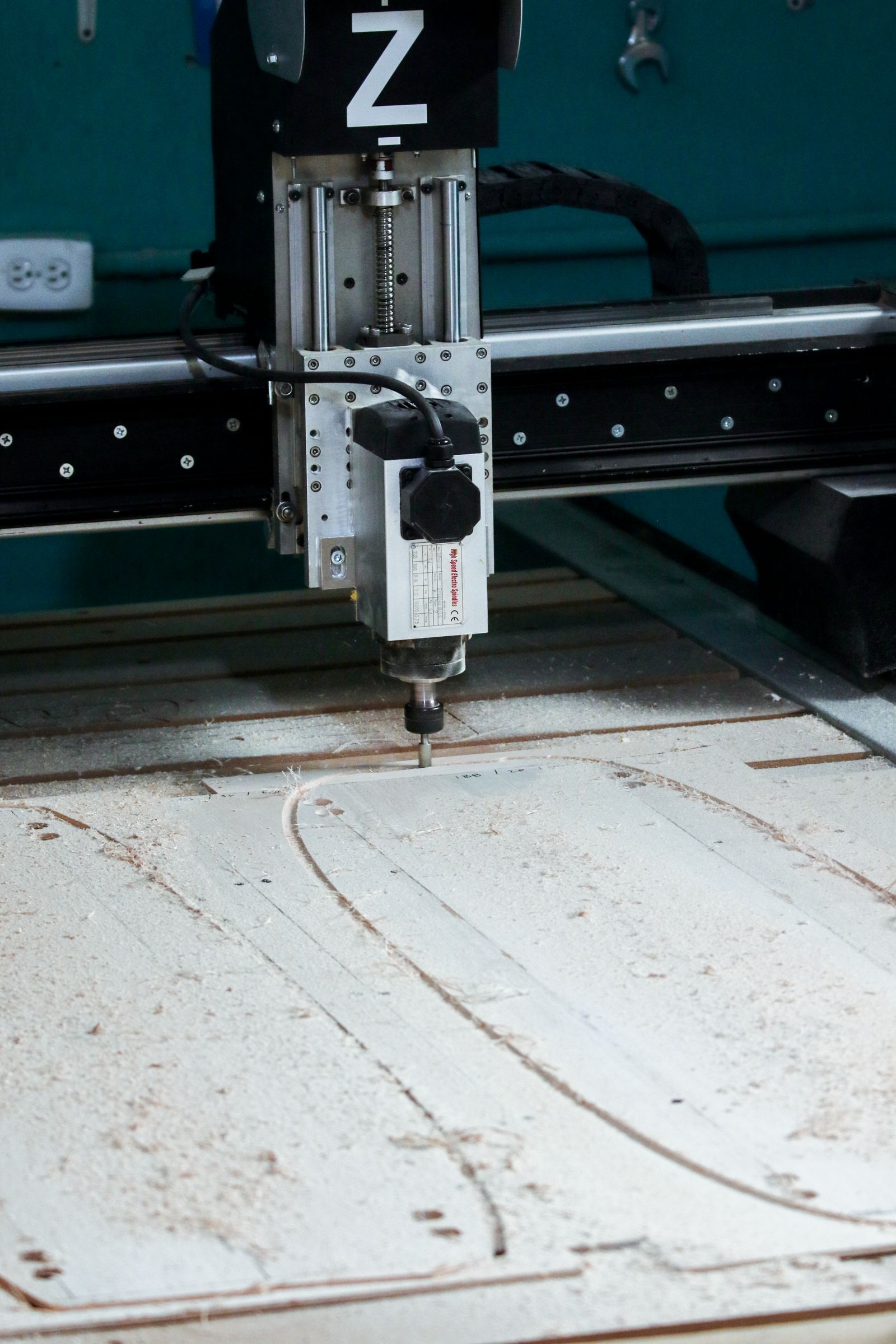
- Micro-EDM (wire and sinker) – Sharp internal corners, deep narrow slots, carbide features.
- Femtosecond / UV laser micro-machining – Sub-25 —m features, polymer ablation, ceramic and glass drilling.
- Micro-milling and micro-drilling – General micro features on metal and plastic with rigid high-resolution spindles.
- Swiss-type turning – Small-diameter, long-aspect-ratio features that pair with face-machined micro features.
- Electropolish and passivation – Surface finish and corrosion resistance on stainless micro parts.
- Micro anodizing (Type I / Type II / Type III) – Hard anodize on aluminum micro features where wear or insulation is required.
- Parylene coating – Conformal insulation and biocompatibility layer on medical micro parts.
- Medical-grade cleaning – Ultrasonic, DI rinse, and clean-room packaging for implants and diagnostics.
- Heat treatment – Vacuum or atmosphere-controlled heat treat for titanium and 17-4 PH micro parts.
- Plating (gold, silver, electroless nickel) – Functional coatings for contact resistance or solderability on micro features.
- Optical / video / SEM / white-light interferometer inspection – Multi-method metrology matched to feature size.
- CMM and laser scanning – For sub-millimeter features that still need 3D data.
- DFM and tolerance-stack-up review – Engineering feedback on the print before production to avoid impossible micro features.
- Sensor housings
- Precision pins and contacts
- Optical mounts
- Micro-fluidic hardware
- Electronics interfaces
When Micro Machining is the Right Choice
Applications include medical devices, electronics, optics, instrumentation, aerospace sensors, miniature automation, and research or prototype development.
Industries & Applications
- Medical devices – minimally invasive surgical instruments, micro-implants, drug-delivery components, micro-endoscope parts.
- Micro-fluidics and lab-on-chip – channel plates, manifold blocks, micro-connector bodies, dispenser components.
- Electronics and semiconductors – probe pins, test sockets, lead frames, micro-connector shells, wafer-handling components.
- Optics and photonics – micro-lens holders, fiber-optic ferrules, kinematic mounts, micro-mirror bodies.
- Aerospace and defense – micro-sensor housings, guidance-system components, micro-actuator parts.
- Robotics and micro-mechatronics – micro-grippers, watch and instrument components, micro-encoder disks.
- Analytical and scientific instruments – chromatography fittings, mass-spectrometer components, sample-handling parts.
Quality plan
Inspection must suit the size of the feature and may require optical methods, microscopes, pin gauges, specialized probes, or functional checks. The acceptance criteria should be stated in a measurable form.
After the machining operation
Protect miniature parts from damage and contamination. Post-processing, marking, and packaging should be planned so they do not deform or obscure delicate geometry.
Release item | Purpose |
|---|---|
Controlled model and drawing | Makes the test or production intent traceable. |
Acceptance method | Confirms that a critical feature can be measured in the way the design expects. |
Learning loop | Captures changes needed before the next prototype, build, or released run. |
Is micro-machining expensive for prototypes?
Micro-machining is more expensive per part than conventional CNC because of small-diameter tooling, slower feeds, and specialized inspection. For prototypes, the cost is usually acceptable because there's no tooling charge and a single setup can deliver the part.
—

