

Engineering question
What must work when the part is real?
Typical part context
Typical prototype components serve product development, fixture trials, pilot automation, service replacement, engineering demonstrations, and low-volume bridge production.
Prototype-to-Production Decisions
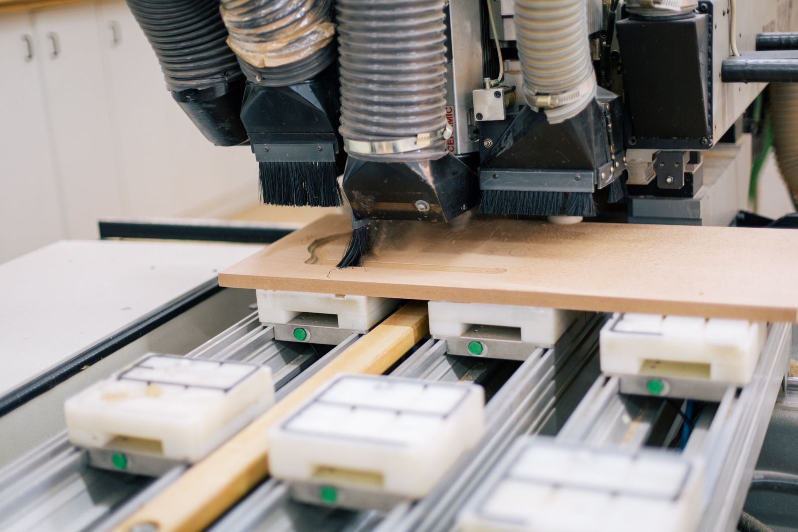
Typical uses include product development, robotics, industrial equipment, aerospace and automotive evaluation, medical devices, electronics enclosures, and custom tooling.
Frequently Asked Questions
What quantities are typical for prototype orders?
Most prototype orders are 1 to 25 parts, but we can run up to a few hundred pieces for low-volume bridge production, pilot builds, or engineering tests.
Purpose | Design validation, fit checks, pilot builds |
|---|---|
Material | Production-relevant grade whenever practical |
Iteration | Fast revisions without hard tooling commitment |
Typical use | Housings, brackets, test fixtures, fit-check assemblies |
Prototype Machining Services
A source-aware reference guide to functional CNC prototypes, DFM feedback, material selection, and the transition from test part to production plan.
Primary concern State what the prototype is intended to prove: fit, strength, flow, motion, thermal behavior, appearance, assembly, or manufacturability. Include revision status, critical interfaces, material grade, and test needs with the RFQ. | Validation lens Inspection should prioritize the features that the prototype is meant to validate. A simple cosmetic sample and a test article for a high-consequence assembly do not need the same acceptance plan. |
|---|
This page uses a design-review opening so the service reads like an engineering brief rather than a repeated product brochure.
What the Prototype Must Prove
Prototype machining produces parts for design validation, functional testing, fit checks, pilot builds, and pre-production learning. It is valuable when the prototype must use a production-relevant material or when the design includes functional geometry that needs to be evaluated before committing to a larger order or dedicated tooling.
Prototype machining produces testable parts in production-relevant materials before tooling commitment.
What is the part proving?
Machining enables rapid design changes without the commitment of hard tooling and can provide a prototype in the actual or representative end-use material.
Design question | Review before machining |
|---|---|
Which feature controls function? | State what the prototype is intended to prove: fit, strength, flow, motion, thermal behavior, appearance, assembly, or manufacturability. Include revision status, critical interfaces, material grade, and test needs with the RFQ. |
What is a successful output? | Inspection should prioritize the features that the prototype is meant to validate. A simple cosmetic sample and a test article for a high-consequence assembly do not need the same acceptance plan. |
Material-Realistic Iteration
Prototypes may include housings, brackets, test fixtures, mechanical interfaces, shafts, enclosures, heat-management parts, fluid components, custom brackets, and complete fit-check assemblies.
Material decision
Aluminum, steel, stainless steel, brass, copper alloys, titanium, and engineering plastics are often considered so the prototype can reflect meaningful mechanical, thermal, electrical, or corrosion behavior.
Design signal: Make critical datums, small or delicate features, and finish-sensitive areas explicit. They should drive the process, not appear as a late exception.
Validation Before the Next Revision
A practical route starts with a CAD and drawing review, identification of test-critical features, selection of material and process, machining of the part, and a documented review of what should change before the next iteration or production release.
Quality plan
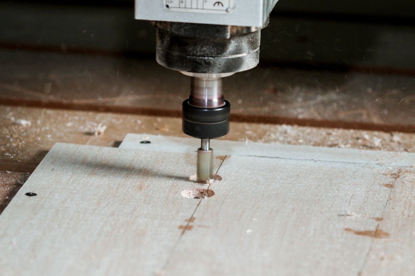
Inspection should prioritize the features that the prototype is meant to validate. A simple cosmetic sample and a test article for a high-consequence assembly do not need the same acceptance plan.
When another route may be better
Choose prototype machining when material realism and functional tolerances matter. For visual form studies or very complex lightweight shapes, other prototype methods may be useful alongside CNC.
RFQ check: Include the job's true objective: fit check, material test, production release, pilot quantity, inspection record, or a combination of these.
Key Process Parameters
Parameter | Typical Value |
|---|---|
Standard tolerance | ±0.05 mm default (ISO 2768-m), ±0.025 mm precision callouts on request |
Surface finish Ra | 0.8 —m to 3.2 —m as-machined, finishing options down to 0.4 —m |
Min feature size | 0.5 mm wall / 0.3 mm slot on most materials; tighter with micro tooling |
Min hole diameter | 0.5 mm standard drills, 0.3 mm with micro drills or EDM |
Max part envelope | Up to 1200 mm — 800 mm — 600 mm; 5-axis parts within trunnion reach |
Available processes | 3-axis, 4-axis, 5-axis milling, CNC turning, turn-mill, Swiss turning, wire EDM, surface & cylindrical grinding, sheet metal (laser, waterjet, brake) |
Typical quantity | 1 to 50 prototypes, low-volume bridge production up to a few hundred |
Standard lead time | 3–7 days for simple parts, 7–15 days for complex multi-operation parts |
Expedited lead time | 24–72 hours on selected simple parts; subject to capacity |
Accepted file formats | STEP, IGES, X_T, SolidWorks native, CATIA, NX, Fusion 360, Inventor, DWG/DXF, PDF drawing; even hand sketches can start the conversation |
Typical machines | Haas VF-2 / VF-4, DMG MORI NHX / DMU 50, Mazak QT / Integrex, Tormach, Hurco, complemented by manual mills and lathes for fast-turn prototypes |
Materials We Machine
- Aluminum alloys – 6061-T6, 7075-T6, 2024-T3, 5052, 6082, MIC6, cast aluminum A356/A380.
- Engineering plastics – ABS, polycarbonate (PC), acrylic (PMMA), Delrin (POM-C / POM-H), HDPE, nylon (PA6 / PA12).
- High-performance plastics – PEEK, Torlon (PAI), PEI (Ultem), PPSU, PSU, PPS, PVDF for engineering prototypes.
- Carbon and alloy steels – 1018, 1045, 4140, 4340, A36, S355.
- Stainless steels – 303, 304/304L, 316/316L, 410, 416, 17-4 PH.
- Tool and die steels – A2, D2, S7, H13, O1, P20, SKD11.
- Brass, copper, and bronze – C360, C110, C932 for prototype electrical and fluid components.
- Titanium – Grade 2 and Grade 5 (Ti-6Al-4V) for functional prototypes and medical demos.
- Magnesium – AZ31 and AZ91 for lightweight prototype structures.
- Cast iron and ductile iron – for prototype engine and machinery components.
- Composite and polymer sheet stock – G10/FR4, Garolite, acrylic, polycarbonate for jigs and fixtures.
Design Considerations (DFM Tips)
- Identify the critical-to-function features – call out dimensions and tolerances that drive the prototype's purpose; leave the rest at ISO 2768-m.
- Add generous fillets and corner relief – 0.5 mm minimum reduces stress, improves tool access, and is friendlier to prototype machining.
- Use standard tooling sizes – metric or imperial standard drills, taps, and reamers reduce cost and lead time.
- Avoid unnecessarily thin walls – 0.8 mm wall is a safe minimum for metal prototypes; 1.0 mm+ is preferred for stiffness and easier fixturing.
- Consider near-net stock – selecting plate, bar, or forging closest to final shape reduces cycle time and material cost.
- Plan for assembly access – prototype parts are often assembled by hand; design for screw access and clearance.
- Use a single setup or one-side machining where possible – reduces fixture complexity and lead time.
- Mark inspection datums on the drawing – even for prototypes, identifying datums avoids ambiguity during measurement.
- Call out cosmetic vs. functional surfaces – they often have different finish and tolerance expectations.
- Keep the design as simple as the function allows – prototypes are an opportunity to remove features that don't earn their cost before tooling investment.
How fast can I get a prototype?
Simple parts in standard materials can ship in 3–5 working days. More complex multi-operation parts typically take 7–15 days. Expedited 24–72 hour service is available for selected parts.
Do you help with design feedback?
Yes. Every prototype quote includes a brief DFM note on tolerance, feature manufacturability, and material. For more complex projects, a written DFM report is available.
How to Get a Quote
Send us your 3D CAD file (STEP, IGES, X_T, or native), a 2D drawing if you have one, the material grade, the desired quantity, the target finish, and any critical tolerances or inspection requirements. We return a DFM review on tolerance, material, and feature manufacturability, a prototype lead time, and a unit price that covers material, machining, inspection, and any finishing.
Process Flow & Manufacturing Sequence
Prototype machining compresses the production planning into a single, fast-turn workflow. The process is the same as a production route, but the priorities shift toward speed, easy iteration, and the ability to change the print between parts. The sequence below is the standard route for a single-piece or low-volume prototype.
- RFQ intake and clarification – Drawing or model is reviewed. If the print is incomplete or not yet released, the prototype shop confirms design intent via email, call, or shared model.
- DFM / producibility review – Quick design-for-manufacturing pass flags tolerance over-spec, untoleranced critical features, impossible callouts, or features that can be simplified. The output is a DFM comment, not a re-design.
- Material selection – A production-relevant material is used whenever possible. Common prototype stocks are 6061-T6 aluminum, 304 / 316 stainless, 1018 / 4140 steel, Delrin, and ABS.
- Quoting and lead-time confirmation – Quote is broken into material, machining, finishing, inspection, and packaging. Lead time is confirmed against the customer's testing or design-review milestone.
- CAM programming – Tool paths are written to balance cycle time and feature accuracy. CAM is often reusable across iterations to shorten re-quote time.
- Stock procurement – Standard catalog sizes are used when possible to avoid raw-material lead time. Special alloys are pre-stocked or sourced from approved suppliers.
- Workholding – Soft jaws, fixture plates, or vises are prepared. For one-off prototypes, machinable wax or double-sided tape is acceptable for non-critical features.
- Rough machining – Aggressive MRR with indexable or solid-carbide tools. Light cleanup is left in corners to keep the program stable.
- Finishing – Sharp tools and light cuts to the print tolerance. Prototype tolerances are typically ISO 2768-m, with tighter callouts where the print requires it.
- Secondary operations – Tapping, deburr, light grinding, or hand-fit are performed as required.
- Surface finishing – Bead blast, anodize, powder coat, plating, or paint is applied per the customer request. Masking is used to protect critical features.
- Inspection – Functional features are measured against the print. A simple dimensional report is included; full CMM / FAIR available on request.
- Customer feedback loop – Prototype is shipped, customer tests or fits the part, and feedback drives the next iteration. CAM programs and fixture data are retained for fast re-quote.
- Iteration / re-quote – Rev A parts can be re-cut within 1–3 days. The CAM operator keeps stateful files so geometry changes do not require full re-programming.
- Marking, packaging, and release – Loose wrap, foam wrap, or individual carton per the customer's shipping preference. C of C issued.
Material Property Reference
Reference property values for materials commonly used in prototype machining. Machinability references AISI 1212 steel at 100%; higher numbers are easier to cut. Plastic values are typical for the unfilled grade unless otherwise noted.
Material | Density (g/cm?) | Tensile Strength (MPa) | Yield Strength (MPa) | Hardness | Machinability Rating (%) |
|---|---|---|---|---|---|
Aluminum 6061-T6 | 2.70 | 310 | 276 | 95 HB | 180 |
Aluminum 7075-T6 | 2.81 | 572 | 503 | 150 HB | 170 |
Aluminum 2024-T3 | 2.78 | 483 | 345 | 120 HB | 170 |
Aluminum MIC6 (cast jig plate) | 2.70 | 240 | 170 | 75 HB | 200 |
Cast aluminum A356-T6 | 2.68 | 230 | 170 | 70 HB | 150 |
Carbon steel 1018 (cold drawn) | 7.87 | 470 | 400 | 140 HB | 78 |
Alloy steel 4140 (annealed) | 7.85 | 655 | 415 | 200 HB | 60 |
Stainless 304 (annealed) | 8.00 | 620 | 290 | 180 HB | 45 |
Stainless 316L (annealed) | 8.00 | 560 | 290 | 170 HB | 40 |
Brass C360 (free-machining) | 8.50 | 510 | 380 | 130 HB | 100 |
Titanium Grade 5 (Ti-6Al-4V) | 4.43 | 950 | 880 | 335 HB | 22 |
Magnesium AZ31 | 1.77 | 240 | 160 | 49 HB | 450 |
ABS (general purpose) | 1.04 | 40 | — | R105 (Rockwell) | — (sharp tools) |
Delrin POM-H (homopolymer) | 1.42 | 70 | — | M94 (Rockwell) | — (sharp tools) |
PEEK (unfilled) | 1.30 | 100 | — | M99 (Rockwell) | — (sharp tools) |
Polycarbonate (Lexan) | 1.20 | 65 | — | R118 (Rockwell) | — (sharp tools) |
Cost Drivers & Lead Time Factors
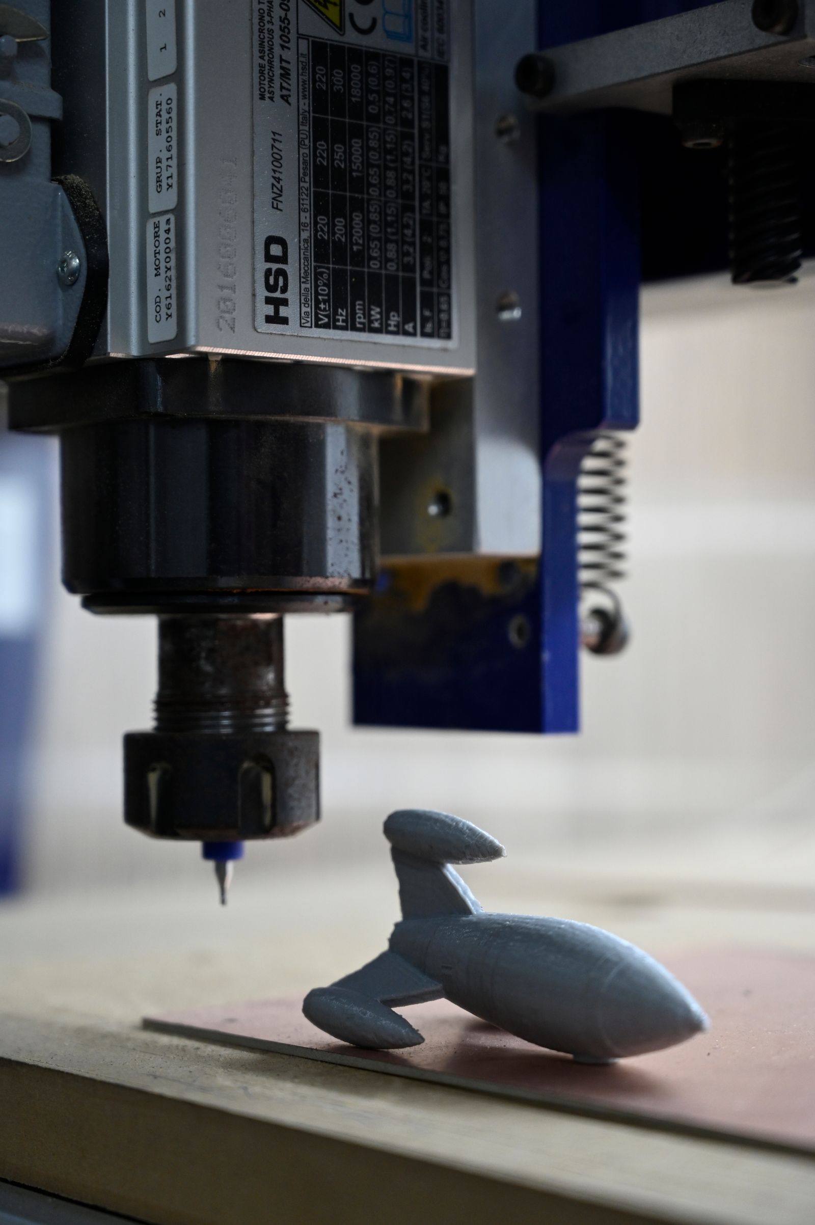
Prototype pricing is dominated by programming, setup, and material yield. Cycle-time efficiencies are limited because the parts are made once. The numbers below are typical for a fast-turn CNC shop with on-shelf stock and standard tooling.
Scenario | Quantity | Typical Lead Time | Primary Cost Drivers |
|---|---|---|---|
Aluminum cosmetic sample, ISO 2768-c | 1–3 off | 24–72 hours | Programming, machine time, finishing |
Stainless functional part, ±0.05 mm | 1–5 off | 3–5 working days | Slower cutting, deburr, passivation |
Aluminum 7075 structural part, ±0.025 mm | 3–10 off | 5–7 working days | Tighter tolerance, anodize, inspection |
5-axis medical concept, ISO 13485 | 3–10 off | 2–3 weeks | 5-axis programming, validated material, CMM |
Plastic fit-check, ABS or Delrin | 1–5 off | 2–4 working days | Material cost, sharp tool wear, finishing |
High-temp plastic demo, PEEK / Torlon | 1–5 off | 5–10 working days | Stock, controlled cutting, dust management |
Bridge production, 50–200 off | 50–200 off | 2–4 weeks | Cycle-time amortization, in-process gauge, packaging |
Multi-iteration (3 revs in 2 weeks) | any | 2–3 weeks total | Concurrent engineering, retained fixtures, quick-turn finishing |
Common Defects & Prevention
Defect | Cause | Prevention |
|---|---|---|
Out-of-tolerance feature | Wrong print revision, programming against an old model, fixturing deflection, machine thermal drift | Lock the print and model at RFQ, run warm-up program, use calibrated soft jaws, verify with in-process gauges |
Cosmetic mismatch with the customer's intent | Surface finish or color not specified, prototype made in wrong alloy, no review of cosmetic requirements | Confirm the cosmetic spec up-front, send a finish sample for color match, photograph the first article before running more |
Burr or sharp edge on a feature the customer will handle | No chamfer callout, dull tool, no deburr step, sharp internal corners | Add chamfer to print or apply standard chamfer, deburr by hand or tumble, replace tools at planned intervals |
Fit-check failure at the customer | Wrong stock allowance, mating part not referenced, tolerance stack-up miscalculated, no datum scheme | Run a tolerance stack-up review, get the mating part or assembly for fit check, define a primary datum on the print |
Wrong material supplied | Spec ambiguous (e.g. "aluminum" with no temper), procurement picked the closest catalog item | Lock the material spec at RFQ, ask for the heat number on the MTC, verify with a quick PMI check on receipt |
Surface finish or color wrong on coated parts | Anodize type / color not specified, no sample swatch, wrong masking | Specify anodize type / color per the print, send a sample swatch, mask critical features, photograph the first part |
Warp or distortion in plastic prototypes | Internal stress in stock, aggressive cutting, no stress relief, moisture in nylon or PEEK | Pre-dry hygroscopic plastics, use sharp tools, take balanced cuts, anneal thick plastic parts if needed |
Iteration time lost between rev A and rev B | CAM programs rewritten from scratch, fixtures scrapped, no retained-state files | Use parametric CAM with a retained project file, re-use soft jaws, keep a fixture library for repeat parts |
Comparison With Related Processes
Aspect | Prototype Machining | Alternative | When to Choose |
|---|---|---|---|
Lead time for 1 part | 3–10 days typical, 24–72 hours on simple parts | Additive manufacturing: 1–3 days, no tooling | Choose additive for geometry-driven prototypes and plastics; machining for functional metal parts |
Material property match | Uses production-grade material: aluminum, steel, stainless, titanium, brass, plastics | Additive: limited material range and anisotropic properties | Choose machining when the prototype must mimic the production material behavior (fatigue, heat, wear) |
Tolerances | ±0.05 mm default, ±0.025 mm on callout | Additive: typically ±0.1–0.2 mm on FDM, ±0.05 mm on SLS / SLA | Choose machining for tight prototype tolerances; additive for visual or fit-only prototypes |
Cost per part at 1 piece | Higher per-part, dominated by programming and setup | Additive: lower per-part at 1 piece for complex geometry | Choose additive for one-off complex plastic prototypes; machining for production-material metal parts |
Surface finish as built | 0.8–3.2 —m Ra on metal; can be polished or finished | Additive: visible layer lines, requires post-processing | Choose machining for cosmetics out of the machine; additive when post-finish time is acceptable |
Packaging, Shipping & Documentation
Prototype parts ship with whatever level of documentation the customer requests — sometimes a single C of C, sometimes a full FAIR. Packaging is sized to the part and to the customer review process.
- Individual wrap – Bubble wrap, foam wrap, or VCI paper for metal parts.
- Anti-static bag – Required for any prototype that will be assembled into an electronic or sensitive assembly.
- Custom foam cavity – Foam-padded box for delicate or high-value prototypes that must survive shipping without cosmetic damage.
- Plain carton – For simple or large parts that do not require cosmetic protection.
- Wooden crate – For prototypes over 25 kg or with delicate features that need rigid support.
- Labeling – Part number, revision, and quantity on each bag; outer carton labeled with project, customer, and any handling instructions.
- Shipping options – Hand-carry for urgent local deliveries, expedited air for tight customer reviews, standard freight for routine prototypes.
- Standard documents – Certificate of Conformance (C of C) keyed to part number and revision.
- Material certificate – MTC or 3.1 / 3.2 inspection certificate per EN 10204 when customer requires.
- Dimensional report – Caliper / micrometer / CMM layout, simple PDF for typical prototypes; FAIR / AS9102 for aerospace or production-first articles.
- Photographs – Color photos of the first part on request, used for cosmetic approval before a run.
- Iteration package – A short summary of changes between rev A and rev B, sent with the next shipment to keep the customer review tight.
After the machining operation
Specify whether the prototype needs raw machining, deburring, cosmetic finish, marking, or a production-representative coating. Consider whether the finish affects dimensions or test behavior.
Release item | Purpose |
|---|---|
Controlled model and drawing | Makes the test or production intent traceable. |
Acceptance method | Confirms that a critical feature can be measured in the way the design expects. |
Learning loop | Captures changes needed before the next prototype, build, or released run. |
Standard Tolerances & Achievable Precision
Prototype tolerances are typically engineering-grade, suitable for fit checks, functional tests, and design verification. Tighter tolerances are available when the application requires them.
- ±0.125 mm standard for non-critical features (ISO 2768-c).
- ±0.05 mm default for most prototype machined features (ISO 2768-m).
- ±0.025 mm precision on functional features and reference surfaces.
- ±0.0125 mm tight tolerance with secondary finishing (grinding, lapping) for critical features.
- ±0.005 mm ultra-precision on selected datums and bearing surfaces.
- Surface finish 0.8 —m to 3.2 —m Ra as-machined, down to 0.2 —m with grinding or polishing.
- GD&T (ASME Y14.5) including true position, profile, runout, and perpendicularity available on request.
Surface Finish Options
- As-machined – visible tool paths, ideal for fit-check prototypes.
- Bead blast (glass bead / aluminum oxide) – uniform matte surface, no dimensional change.
- Light tumbling / vibratory finishing – deburrs sharp edges on small machined parts.
- Anodize Type II (sulfuric) – decorative and corrosion-resistant on aluminum.
- Anodize Type III (hard anodize) – wear-resistant, thicker coating on aluminum parts.
- Powder coat – durable, color-matched finish on metal prototypes and housings.
- Wet paint and primer – for cosmetic appearance and color matching.
- Electroplating – zinc, nickel, chrome, tin, gold for prototypes that mimic production finishes.
- Electroless nickel – uniform deposit on complex geometries, useful for functional testing.
- Passivation – ASTM A967 / A380 on stainless steel prototypes.
- Black oxide and manganese phosphate – on steel prototypes for cosmetic and corrosion resistance.
- Polishing and buffing – mirror or satin finish on stainless and aluminum cosmetic parts.
- Laser engraving and laser marking – part numbers, scale marks, and logos on flat or slightly curved surfaces.
Quality Control & Inspection
Prototype inspection balances speed with accuracy. We confirm critical dimensions and surface finish while keeping turnaround short.
- CMM (Zeiss, Hexagon, Mitutoyo) – full dimensional and GD&T verification on critical prototypes.
- Calipers, micrometers, and depth gauges – 0.01 mm resolution for general dimensional checks.
- Pin gauges and bore gauges – for hole and slot verification.
- Optical comparator / vision system – for profile, chamfer, and edge break.
- Surface roughness comparator or tester – Mitutoyo SJ-series for measured surface finish.
- Hardness tester – for prototype parts that include heat-treat or surface-hardened features.
- First-article inspection (FAIR / AS9102 or simplified report) – documented for engineering review and sign-off.
- Photographs and inspection summary – included in the standard delivery for visual review.
Do I need a drawing to order a prototype?
A 3D CAD file is enough to start. We can extract most tolerances and surface finish from the model. A 2D drawing is helpful for tight tolerances, GD&T, and inspection-critical features.
Can you do cosmetic finishes for marketing samples?
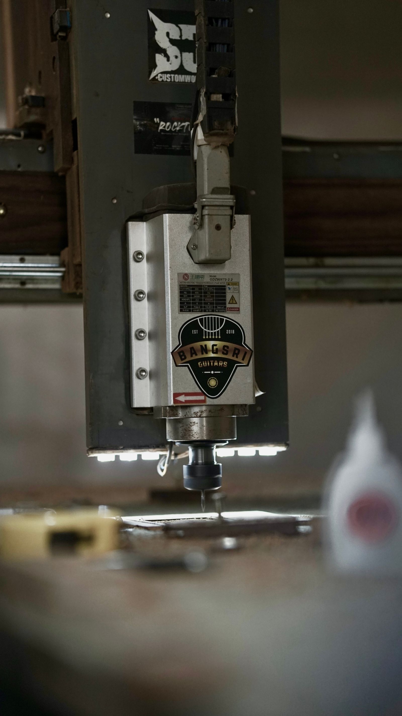
Yes. We can apply anodize, powder coat, painting, polishing, plating, and laser marking for cosmetic prototypes, design-review models, and trade-show samples.
Related Capabilities & Cross-Services
Prototype work is often the first step in a longer customer journey, and the capabilities below pair naturally with a prototype run to add functional or cosmetic features, or to bridge the prototype into low-volume production.
- 3-, 4-, and 5-axis CNC milling – Prismatic parts, complex contours, and prototype housings.
- CNC turning and mill-turn – Turned features, prototype shafts, and fittings.
- Swiss-type turning – Small-diameter prototypes for medical, electronics, and fluid power.
- Cylindrical and surface grinding – Tight-tolerance features on the prototype when machining alone cannot reach the print.
- Wire EDM and Sinker EDM – Sharp inside corners, small slots, and hardened prototypes.
- Sheet metal (laser, waterjet, brake) – Brackets, enclosures, and panels that pair with a machined part.
- Anodizing, powder coating, and wet paint – Cosmetic finishing for visual approval or for prototypes that will be assembled into a finished product.
- Plating (chrome, electroless nickel, gold, silver) – Functional and decorative coatings on metal prototypes.
- Passivation and electropolish – Surface conversion on stainless prototypes for medical or food-grade parts.
- Heat treatment – Hardening or tempering for prototypes that need to test production heat-treat behavior.
- CMM and optical metrology – Functional-feature inspection, signed off before the prototype is released.
- DFM review and tolerance stack-up analysis – Engineering feedback to the customer before the production print is released.
- Bridge production and pre-production runs – 50–500-piece low-volume build before tooling investment.
- Housings and brackets
- Test fixtures
- Fit-check assemblies
- Engineering demonstrations
- Low-volume bridge production
Industries & Applications
- Product development and R&D – functional prototypes, proof-of-concept hardware, design verification builds.
- Automotive – prototype engine components, EV battery and motor housings, bracketry, jigs and fixtures.
- Aerospace – non-flight test hardware, engineering demonstration units, ground-support equipment.
- Medical and life sciences – device prototypes, ergonomic test models, surgical-instrument pre-production parts.
- Robotics and automation – end-effector components, sensor mounts, structural frames, test fixtures.
- Consumer electronics – housings, internal brackets, prototype tooling, industrial-design samples.
- Industrial machinery – machine sub-assemblies, prototype tooling, gauge hardware, retrofit components.
- Energy – turbine hardware pre-production, fuel-cell plate prototypes, instrumentation parts.
Industry Standards & Certifications
- ISO 9001:2015 – QMS baseline for prototype shops of any industry.
- AS9100D – Aerospace QMS for prototypes destined for aerospace qualification or for parts used in flight-test articles.
- ISO 13485:2016 – Medical-device QMS for prototypes used in design verification, animal studies, or first-in-human trials.
- IATF 16949 – Automotive QMS for prototypes that feed into PPAP / APQP.
- RoHS & REACH – Compliance for European prototypes in electrical, electronic, or consumer products.
- ITAR – Required for defense prototypes and any controlled data or articles.
- ISO 2768-1 / ISO 2768-2 – General-tolerance reference for un-toleranced features on prototype drawings.
- ASME Y14.5-2018 – GD&T symbol set used on prototype prints that already follow production GD&T.
- ISO 5459 – Datum reference convention applied to prototypes when a datum scheme is called out.
- SAE AS9102 – First-article inspection report when the prototype is the first article of a future production run.
- AIAG PPAP / APQP – Used when the prototype is the first step in an automotive production approval.
- ISO 10360 – CMM acceptance test applied to any CMM used in prototype inspection.
Can you switch to production volumes after the prototype?
Yes. Once the prototype is approved, we can scale to production using the same process, with the option to optimize fixturing and add DFM-driven cost reductions for higher quantities.

