

Warum dieses Verfahren wählen
Boring provides more control over final hole geometry than a rough drilled hole. It is useful when an internal feature needs to locate, support, seal against, or rotate with another precision component.
Häufig gestellte Fragen
Do you do stepped or multiple bores in one setup?
Yes. Multi-step and coaxial bore pairs are machined in a single setup to keep concentricity and avoid re-fixturing error. The print should call out the relationship between the bores so the process can be planned around it.
Can you bore hardened parts?
Up to about HRC 45–50 with coated carbide or CBN tooling. Above that we recommend grinding or EDM for the final bore. If a part is supplied hardened, send the hardness spec with the drawing so the right process is selected.
—
Was der Prozess bewirkt
CNC boring is a precision hole-machining process used to control the final size, position, alignment, and surface condition of an existing hole. A boring tool removes a controlled amount of material from a drilled or pre-machined opening, making the process useful when the required bore is more demanding than a drilled hole alone.
Prozessfluss
Die Bearbeitungssequenz sollte um die funktionalen Bezugselemente des Teils', den Merkmalzugang, das Materialverhalten und die erforderliche Prüfmethode geplant werden. Die detaillierte Route wird letztendlich durch die tatsächliche Maschinenkonfiguration, Werkstückspannung, Werkzeugverfügbarkeit und Produktionsmenge bestimmt.
Prozessstufe | Zweck |
|---|---|
1. Eingabe überprüfen | Bestätigen Sie das 3D-Modell, die Zeichnung, das Material, kritische Abmessungen, Bezüge, Mengen und Oberflächenanforderungen. |
2. Einrichtungsplan | Wählen Sie Werkstückspannung, Bezugsstrategie, Schneidwerkzeuge, Bearbeitungsreihenfolge und Zugang zu allen funktionalen Merkmalen. |
3. Bearbeitung | A typical route establishes a reliable datum, creates or locates the initial hole, and then uses a boring tool to machine the final bore. The chosen strategy depends on depth, diameter, tolerance, accessibility, stiffness, and the relationship of the bore to adjacent features or another bore. |
4. Verifizierung | Inspection may include diameter, roundness, cylindricity, bore depth, axis location, concentricity, perpendicularity to a face, and surface condition. The measurement method should match the tolerance and accessibility of the hole. |
Designabsicht
A bore should be specified with its final diameter, tolerance, depth, datum relationship, coaxiality or positional requirement, entry chamfer, and surface finish. For a bearing or seal, identify the mating component and the intended fit class.
ENGINEERING-EINGABE ?Stellen Sie ein 3D CAD-Modell bereit, eine Zeichnung mit kritischen Toleranzen und Bezügen, die Werkstoffgüte, die angeforderte Menge, die Oberflächenbeschaffenheit sowie sämtliche Prüf- oder Verpackungsanforderungen. |
|---|
Bauteilgeometrie und Werkstoffe
Werkstoffauswahl
Aluminum, steel, stainless steel, cast iron, brass, bronze, titanium, and engineering plastics can all require boring when final fit and position are important. Material behavior affects tool selection, vibration control, and surface finish.
Werkstoffgruppe | Zu berücksichtigen | Typischer Auswahlgrund |
|---|---|---|
Aluminium | Zerspanbarkeit, thermische Ausdehnung, optische Oberfläche. | Leichte Gehäuse, Halterungen, Vorrichtungen, Wärmemanagement-Bauteile. |
Stahl & Edelstahl | Festigkeit, Korrosionsbeständigkeit, Hitze, Spankontrolle. | Industrie-, Struktur-, Fluid- und Präzisionsmechanikbauteile. |
Messing, Kupfer & Titan | Leitfähigkeit, Korrosion, Festigkeits-Gewichts-Verhältnis, Kosten. | Anschlüsse, elektrische Teile, Hochleistungs- oder Spezialbauteile. |
Technische Kunststoffe | Steifigkeit, Temperatur, chemische Umgebung, Gratbildung. | Isolierende, leichte, Prototyp-, Verschleiß- oder Fluidkontaktteile. |
MATERIALHINWEIS ?Das Material muss zuerst nach funktionellen Anforderungen ausgewählt werden. Zerspanbarkeit, Wärme, Korrosion, Gewicht, Kosten und die gewünschte Oberflächenbehandlung sollten dann gemeinsam überprüft werden. |
|---|
Technische Planung und Qualität
Vor der Produktion
Eine Fertigungsbarkeitsprüfung sollte bestätigen, dass das Toleranzschema funktionell ist, das angegebene Material verfügbar ist, die Werkstückaufnahme den Zugang zu kritischen Flächen ermöglicht und der Messplan alle Anforderungen eindeutig verifizieren kann. Wenn eine Baugruppenschnittstelle kritisch ist, geben Sie die Informationen zum Gegenstück oder die Passanforderung an.
ZEICHNUNGSPRAXIS ?Nennen Sie die Maße, die für die Funktion entscheidend sind. Vermeiden Sie unnötig enge Allgemeintoleranzen, wenn nur eine begrenzte Anzahl von Merkmalen die Passung, Bewegung, Abdichtung oder Ausrichtung der fertigen Baugruppe bestimmt. |
|---|
Anwendungskontext
Power transmission, industrial machinery, robotics, fluid handling, automotive, aerospace, automation fixtures, and precision instrumentation commonly rely on bored features.
Anwendungsfamilie | Wo der Prozess Mehrwert schafft |
|---|---|
Prototypen- und Produktentwicklung | Nützlich, wenn ein funktionales Teil, ein Prüfmuster oder ein Prozessweg validiert werden muss, bevor eine größere Produktionsentscheidung getroffen wird. |
Industrie- und Automatisierungsausrüstung | Unterstützt langlebige kundenspezifische Hardware, Vorrichtungen, Gehäuse, Schnittstellen, Wellen, Durchführungen und Montagemerkmale. |
Präzisions- und Regelungsausrüstung | Unterstützt Geometrien, die durch klare Bezugspunkte, Materialspezifikationen, Prüfanforderungen und kontrollierte Oberflächenbearbeitung dokumentiert werden müssen. |
Wann ein anderes Verfahren gewählt werden sollte
Choose boring when a hole must meet a controlled final size, alignment, or finish requirement. For a threaded hole, tapping may be needed; for a close-fit plain hole, reaming can also be considered depending on the geometry and tolerance.
ANGEBOTS-CHECKLISTE ?Modell- und Zeichnungsdateien, Materialgüte, Bestellmenge, Materialzertifizierungsanforderungen, Oberflächenbearbeitungsanforderungen, kritische Merkmale und Zieldatum der Lieferung mit der Anfrage beifügen. |
|---|
Wichtige Prozessparameter
Parameter | Typischer Wert |
|---|---|
Durchmesserbereich | ?3 mm to ?500 mm (small-bore on VMC / lathe; large-bore on dedicated boring machines) |
Durchmessertoleranz | ±0.013 mm precision; ±0.025 mm standard; ±0.05 mm general |
Roundness | 0.005–0.020 mm depending on tool, material, and bore depth-to-diameter ratio |
Cylindricity | 0.010–0.030 mm across the bore length |
Oberflächenfinish | Ra 0.4–1.6 µm as-bored; finer with finishing passes or secondary honing |
Concentricity / coaxiality | 0.01–0.03 mm between bores or between a bore and an external diameter |
Maximum depth-to-diameter | Up to 10:1 standard; deeper bores evaluated with extended tool holders or special fixturing |
Boring tool types | Single-point boring bars, indexable roughing / finishing heads, fine-boring heads with diameter adjustment |
Maschinenplattform | 3-axis / 4-axis VMC, horizontal boring machine, turning centre with live tooling, dedicated fine-boring cell |
Losgröße | Single-piece prototypes through 10,000-piece production runs |
Typische Lieferzeit | 5–10 working days prototypes; 10–25 working days production |
Akzeptierte CAD-Formate | STEP, IGES, X_T, Parasolid, native SolidWorks / CATIA / NX / Fusion 360 |
Materialien, die wir bearbeiten
- Aluminum alloys — 6061-T6, 7075-T6, 2024-T3, 6082, 5052, A356, A357 castings
- Carbon and alloy steels — 1018, 1045, 4140 pre-hard, 4340 Q&T, EN24, EN26
- Stainless steels — 303, 304 / 304L, 316 / 316L, 321, 347, 17-4PH, 15-5PH, 2205 duplex
- Tool steels and bearing steels — A2, D2, O1, S7, H13, 52100
- Cast iron and ductile iron — gray iron GG25, ductile iron 60-40-18, ADI grades
- Brass, bronze, and copper — C360 brass, C932 bearing bronze, C954 aluminium bronze, C110 copper
- Titan — Grad 2, Grad 5 (Ti-6Al-4V), Grad 5 ELI
- Engineering plastics — POM (Delrin), PEEK, PTFE, nylon, polycarbonate for non-metallic bearing seats
Standardtoleranzen & erreichbare Genauigkeit
Boring is the right process when a hole must be controlled to a final size, location, and finish beyond what drilling alone delivers. The achievable accuracy depends on the depth-to-diameter ratio, the stiffness of the setup, and the material.
- Diameter: ±0.025 mm standard, ±0.013 mm on precision bores, ±0.05 mm general tolerance
- Roundness: 0.005–0.020 mm depending on bore size and material
- Cylindricity: 0.010–0.030 mm across the bore length
- Concentricity between bores: 0.01–0.03 mm
- Position relative to a datum: ±0.025 mm, with full GD&T on request
- Perpendicularity to a reference face: 0.02–0.05 mm / 100 mm
- Default linear tolerance per ISO 2768-m if the drawing does not call out otherwise
Qualitätskontrolle & Prüfung
Inspection is selected to match the bore's tolerance and accessibility. Bores below ?6 mm require special equipment; very deep bores are checked with air gauges or bore gauges designed for that range.
- CMM for diameter, position, concentricity, perpendicularity, and other GD&T features
- Internal diameter gauges, bore gauges, and air gauges for size and roundness
- Surface roughness tester for Ra on accessible bores
- Hardness tester (Rockwell / Vickers / Brinell) for heat-treated bores and bearing seats
- Digital calipers, micrometers, and depth gauges for shop-floor checks
- First-article inspection against the full drawing; in-process checks at rough and finish stages
- Endinspektionsbericht und Materialzertifizierung (EN 10204 3.1) auf Anfrage
Designüberlegungen (DFM-Tipps)
- Always specify the start condition for the bore: drilled, cast, forged, or pre-machined. The starting allowance drives tool choice and final accuracy.
- Keep bore depth-to-diameter within 10:1 for routine boring; deeper bores need an extended tool holder and a stability review.
- Indicate which bore is the primary datum so the fixture and tool plan are built around a single reference.
- Add a chamfer or entry radius at the bore mouth — it protects the tool on entry and helps alignment of mating parts.
- For stepped bores, dimension each step clearly. Avoid tight tolerance on a deep step where a finish-boring pass can be done after roughing.
- If the bore is a bearing or seal seat, name the mating component and the fit class (H7/g6, H6/h5, etc.) on the print.
- Tight diameter tolerance on a long bore drives up cycle time — flag any feature that genuinely needs precision versus features that only need to be controlled loosely.
- For thin walls, leave enough material to avoid deflection under boring forces; flag the wall thickness on the print.
- Where a bore must align with an external diameter, call out concentricity or coaxiality — it sets the inspection method, not just the part geometry.
How accurate is CNC boring?
Standard boring holds ±0.025 mm on diameter with 0.005–0.020 mm roundness. With fine-boring heads, repeatability is closer to ±0.005 mm on small and mid-range bores. The exact result depends on the depth-to-diameter ratio, material, and the machine.
What information is needed to quote a boring job?
The 3D model, drawing with GD&T, material grade and hardness, start condition for the bore (drilled / cast / forged), order quantity, and any required surface finish or inspection report. With those, we can recommend the right process and the most stable fixturing strategy.
So erhalten Sie ein Angebot
Send the 3D model, 2D drawing with GD&T, material grade, start condition for the bore, order quantity, and any surface finish, plating, or inspection requirements. For tight tolerance or large bores, include hardness spec and the mating component so we can recommend the right tool and process.
You receive a written quote within one working day including DFM feedback, the proposed boring and inspection route, lead time, and unit price. Where a secondary operation (honing, grinding, fine-boring) gives a better result at lower cost, it is called out in the quote.
Prozessablauf und Fertigungsabfolge
A CNC boring operation is built around an existing hole — drilled, cast, or pre-machined — that must be enlarged and finished to a controlled size, position, and surface. The sequence below is the standard route; the actual selection of tool, machine, and parameters is set by the part's diameter, depth, and material.
- Review the print and starting condition — confirm the starting bore size, material, hardness, and any prior operations (drilled, cast, forged, or rough-bored); the starting allowance drives tool selection.
- Workholding and datum set — the part is clamped in a vice, fixture, or chuck; the primary boring datum is set to a known face, bore, or OD so size and position reference the same geometry throughout the cut.
- Tool selection — single-point boring bar for general work, indexable roughing head for heavier stock, fine-boring head with micron adjustment for tight tolerance and finish.
- Rough boring — heavy stock is removed with a stepped roughing tool or a carbide bar; radial depth-of-cut is balanced against chatter and machine power.
- Semi-finish boring — leaves a small, uniform stock allowance (typically 0.2–0.5 mm on diameter) for the finish pass and reduces deflection in the final cut.
- Finish boring — final size is reached with a sharp, light-cut tool, controlled chip load, and a dwell at the bore mouth to clean up the exit.
- Edge break and chamfer — a 0.2–1.0 mm chamfer is added at the entry and exit to protect the bore and ease assembly.
- In-process gauging — bore size, roundness, and (where possible) cylindricity are checked between rough and finish passes; the fine-boring head is adjusted as needed.
- Secondary finishing — honing, lapping, or burnishing is performed when the print calls for very fine finish, sub-5 µm roundness, or controlled surface texture.
- Final inspection and documentation — size, position, geometric tolerances, and surface finish are measured against the print and recorded on the inspection report.
Materialeigenschaftsreferenz
Material | Dichte (g/cm³) | Zugfestigkeit (MPa) | Streckgrenze (MPa) | Härte (HB) | Zerspanbarkeit (%) |
|---|---|---|---|---|---|
Aluminium 6061-T6 | 2.70 | 310 | 276 | 95 | 180 |
Aluminium 7075-T6 | 2.81 | 572 | 503 | 150 | 160 |
Messing C360 (automaten) | 8.50 | 400 | 140 | 80 | 100 |
Stahl 1018 (kaltgezogen) | 7.87 | 440 | 370 | 130 | 70 |
Stahl 4140 vorgehärtet (HRC 28–32) | 7.85 | 1,020 | 900 | 290 | 55 |
Stahl 4340 vergütet (HRC 28–34) | 7.85 | 1,100 | 1,000 | 320 | 50 |
Edelstahl 304 / 304L | 8.00 | 580 | 290 | 170 | 45 |
Edelstahl 17-4PH (H900) | 7.78 | 1,310 | 1,170 | 380 | 35 |
Werkzeugstahl D2 (geglüht) | 7.70 | 760 | 450 | 220 | 30 |
Cast iron GG25 (gray) | 7.20 | 250 | — (brittle) | 180 | 80 |
Gusseisen mit Kugelgraphit 60-40-18 | 7.10 | 414 | 276 | 150 | 85 |
PEEK (unfilled) | 1.32 | 100 | 70 | — (Rockwell M99) | N/V (Kunststoff) |
Kostentreiber & Lieferzeitfaktoren
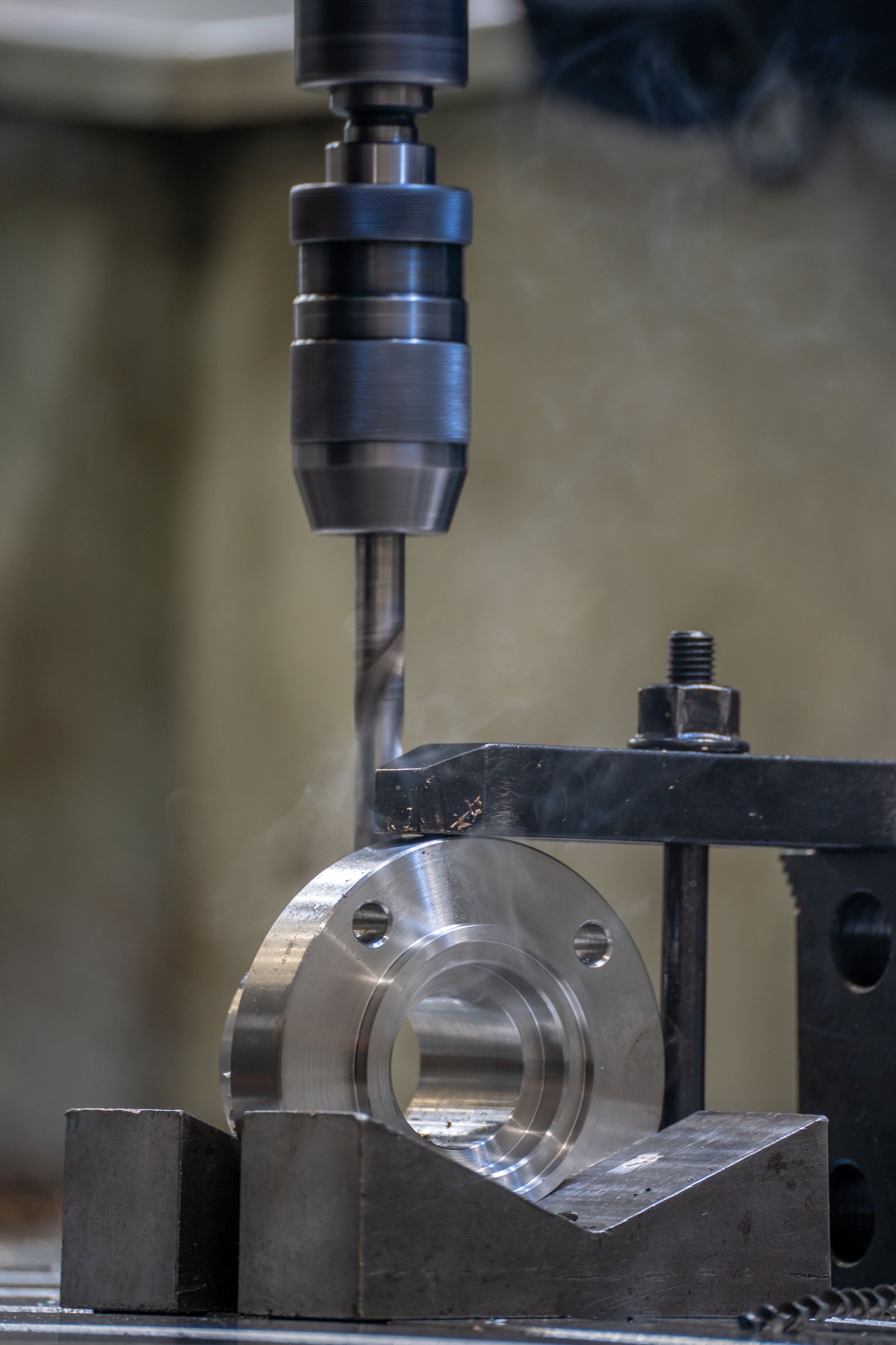
Boring cost and lead time are driven by the starting bore condition (cast, forged, or drilled), the diameter and depth-to-diameter ratio, the required tolerance and surface finish, and any secondary finishing such as honing. Tooling cost is moderate — boring uses standard bars and heads — but precision boring adds gauging and trial-cut time.
Szenario | Typische Lieferzeit | Hauptfaktor |
|---|---|---|
Prototype, standard tolerance, in-stock material | 5–7 Arbeitstage | Programming, setup, first-article bore check |
Prototype with honed finish (Ra < 0.4 µm) | 7–12 Arbeitstage | Honing tool setup, abrasive selection, roundness verification |
Large-bore (> ?200 mm) on horizontal boring machine | 7–14 working days | Machine scheduling, boring head procurement, fixturing |
Produktion 50–500 Stück | 10–18 Arbeitstage | Cycle time, boring head wear, in-process gauging |
Produktion 500–5,000 Stück | 15–25 Arbeitstage | Multi-machine scheduling, fixture repeatability, scheduled head changes |
Gehärtetes Teil, HRC 45–55 | +5–10 Arbeitstage ggü. Baseline | CBN / ceramic tools, slower parameters, additional inspection |
Multi-step or coaxial bore in one setup | +2–5 Arbeitstage vs. Baseline | Tool stations, alignment between steps, inspection plan |
Branchenstandards und Zertifizierungen
- ISO 9001:2015 — Qualitätsmanagementsystem für alle Produktionsarbeiten
- AS9100D — aerospace QMS for landing-gear, actuator, and engine-mount bores
- ISO 13485:2016 — medical device QMS for instrument pivot bores and implant-related bores
- IATF 16949 — automotive QMS for engine, transmission, and chassis bores
- ISO 2768 (general tolerances) and ISO 286 (limits and fits) for default tolerancing on bores
- ASME Y14.5 and ISO 5459 for GD&T on position, cylindricity, concentricity, and perpendicularity
- RoHS, REACH, and DFARS compliance on material sourcing and plating
- ITAR registration for defence-related boring work
- ISO 4406 / NAS 1638 for fluid cleanliness on hydraulic and pneumatic bores
Verpackung, Versand & Dokumentation
Bored parts are packed to protect critical bores from contamination, impact, and corrosion. Bearing or seal bores are usually wrapped individually with VCI paper, plugged, or capped, and a desiccant pack is added for long-distance shipments.
- Standard packaging — VCI wrap, individual foam, layer-pad cartons, or custom trays for delicate or large parts; bore plugs or caps on request for precision bores.
- Custom packaging — customer-specified dunnage, kitting, and labelled bags per part number; crates and braces for large housings.
- Versandoptionen — Luftfracht, Seefracht (FCL/LCL), Straße und Kurier; EXW-, FOB-, CIF- und DAP-Incoterms werden unterstützt.
- Standarddokumente — Packliste, Handelsrechnung, Konformitätszertifikat (C of C), Werkstoffprüfzeugnis nach EN 10204 3.1.
- Inspection documents — first-article report (AS9102 / PPAP), full dimensional report with CMM data, bore-size and roundness log, surface-finish and hardness results.
- Traceability — heat- and lot-number linkage from raw stock through boring, heat-treat, finishing, and shipping; serialisation on request.
Fertigungsüberlegungen
A bore should be specified with its final diameter, tolerance, depth, datum relationship, coaxiality or positional requirement, entry chamfer, and surface finish. For a bearing or seal, identify the mating component and the intended fit class.
Qualität und Prüfung
Inspection may include diameter, roundness, cylindricity, bore depth, axis location, concentricity, perpendicularity to a face, and surface condition. The measurement method should match the tolerance and accessibility of the hole.
Oberflächenfinish und Teileschutz
Bore surfaces are usually protected during any subsequent cosmetic finishing process. If an external coating is needed, critical bores may need masking or a controlled post-finish operation.
Oberflächenfinish-Optionen
- As-bored internal finish, typical Ra 0.4–1.6 µm
- Fine-boring pass for Ra 0.2–0.8 µm and tighter size control on bearing / sealing bores
- Honing for hydraulic bores requiring Ra below 0.4 µm and roundness under 5 µm
- Bore burnishing for hardened bushings and food-grade stainless surfaces
- External finishes: as-machined, bead blast, anodize Type II / III, powder coat, paint
- Electroplating: zinc, zinc-nickel, nickel, tin, chrome (decorative and hard chrome)
- Passivation for stainless steels (ASTM A967 / A380), black oxide for carbon steels
- Polishing, lapping, and laser marking for cosmetic or traceability requirements
What is the difference between boring and drilling?
Drilling creates the initial hole. Boring enlarges and finishes an existing hole to a controlled final diameter, position, roundness, and surface finish. Use boring whenever the print calls for closer tolerance, better roundness, or a specific fit.
Häufige Defekte und Prävention
Defekt | Ursache | Prävention |
|---|---|---|
Bore taper | Boring bar deflection, uneven starting bore, or thermal growth during the cut | Use a stiffer bar, reduce tool projection, take a finish pass with a sharp insert, and verify coolant temperature |
Chatter marks on bore wall | Low rigidity setup, excessive radial depth, or harmonics between bar and toolholder | Use a shorter and larger-diameter bar, add a tuned anti-vibration holder, reduce radial engagement, and verify holder runout |
Oversize or undersize bore | Tool wear, thermal drift, or incorrect diameter offset on the fine-boring head | Replace inserts on schedule, measure bore between passes, recalibrate the fine-boring head, and stabilise coolant temperature |
Poor roundness | Asymmetric starting bore, poor workpiece clamping, or one-sided insert wear | Pre-machine the starting bore round, balance the clamping, rotate the insert index, and use a fine-boring head for tight roundness |
Position error (off-location) | Spindle runout, fixture stack-up, or wrong datum reference | Indicate the part in the fixture, use a single datum reference, and verify machine thermal compensation |
Burr at bore mouth | Exit conditions of the boring bar, dull cutting edge, or excessive feed at exit | Add a chamfer pass at the bore mouth, reduce feed at exit, and add a deburr cycle as required |
Built-up edge on aluminium and stainless | Low cutting speed or wrong tool coating | Increase cutting speed, switch to a polished and coated insert, and use high-pressure through-tool coolant |
Oberflächenfinish außerhalb der Spezifikation | Vibration, feed rate too high, or incorrect nose radius on the insert | Reduce feed to match the print's Ra target, increase nose radius, and add a final light skim pass |
Vergleich mit verwandten Verfahren
Aspekt | CNC Boring (this process) | Drilling | Reaming |
|---|---|---|---|
Starting condition | Requires an existing hole | Creates the hole from solid | Requires a pre-drilled or pre-bored hole |
Diameter control | Continuous, ±0.013 mm with fine-boring head | Limited to standard drill sizes | Fixed at standard reamer size |
Durchmesserbereich | ~?3 mm to ?500 mm+ | ~?0.5 mm to ?50 mm standard | ~?1.0 mm to ?50 mm standard |
Oberflächenfinish | Ra 0.4–1.6 µm as-bored, finer with honing | Ra 1.6–6.3 µm typisch | Ra 0.4–1.6 µm as-reamed |
Flexibility on size | Adjustable in-cycle, ideal for prototype and mixed sizes | Limited to drill inventory | Requires a reamer per size |
Beste Eignung | Large bores, tight tolerance, prototypes, custom sizes | Initial hole creation, shallow bores, high volume | High-volume finishing of small to mid bores at standard sizes |
Zugehörige Fähigkeiten & Querschnittsdienste
CNC boring is rarely the only operation on a part. The following capabilities are typically combined with boring to produce a finished, inspected component.
- Drilling and deep-hole drilling — creating the starting bore or the deeper fluid passages in the part envelope.
- Reaming — finishing of small to mid-range bores at standard H-class sizes for high-volume production.
- Honing and lapping — controlled roundness, sub-5 µm finish, and plateau surface texture for hydraulic and bearing bores.
- Cylindrical and surface grinding — finishing of external diameters, shoulders, and reference faces that work with the bore.
- Milling (3-axis, 4-axis, 5-axis) — features on the part envelope and intersecting ports that align with the bore.
- Tapping and thread milling — internal threads at the bore mouth and cross-port threads for fasteners.
- Heat treatment — through-hardening, case-hardening, induction hardening, and stress relief through approved partners.
- Surface finishing — passivation, nitriding, black oxide, hard chrome, electroless nickel, and internal coatings for wear and corrosion.
- Cleanliness verification — flushing, ultrasonic cleaning, and lab cleanliness testing for fluid-power assemblies.
- Assembly and pressure testing — pressing bushings and bearings, sub-assembly of ports, and hydrostatic / pneumatic testing.
Features and Typical Components
Boring is commonly specified for accurate internal diameters, stepped bores, coaxial bore pairs, bearing seats, sealing bores, precision locating features, and holes that must align with a mating shaft, insert, or housing.
Typical components ?Typical parts include bearing housings, gearbox cases, motor end covers, valve bodies, pump housings, fixture plates, machine bases, adapter blocks, and precision industrial enclosures.
Advantages and Applications
Industries & Applications
- Aerospace — hydraulic actuator bodies, landing-gear trunnions, engine mount bores, valve bodies
- Automotive — gearbox housings, differential cases, brake caliper bores, engine cylinder bores
- Hydraulics and fluid power — valve spools, pump bodies, manifold blocks, hydraulic cylinder end caps
- Industrial machinery — bearing housings, gearbox covers, pinion shafts, mounting flanges
- Energy — turbine casings, generator housings, oil & gas valve bodies, pump casings
- Medical devices — surgical instrument pivot bores, imaging equipment housings, instrument handles
- Robotics and automation — servo-mount bores, robot joint housings, gear reducer bodies
—
Can you bore large diameters?
Yes. Bores above ?200 mm are typically produced on a horizontal boring machine or a large VMC with a boring head. We review the part envelope and machine selection during the quote so the right equipment is scheduled.

